Do I need to get an evaluation board?
It’s up to you to determine whether to get an eval board or not; I’m choosing to get one so that I can begin my software development without having to wait for my board design and the fabrication of the boards. Additionally, I anticipate that I’ll make quite a few mistakes on the first revision of the board, so it’ll be very helpful to have a working board to compare against when something isn’t going as intended – it’ll help suss out whether the issue is software/configuration related or if the custom hardware is problematic. If you’re reading this in the future and I already have a “working” board design that you can make, I think the evaluation board loses some of its value. However, consider that if you don’t get one, you’ll have to get a $22 ST-Link Programmer; the cost of the evaluation board is $32 and it can be used to program another board, so I think it could be a pretty worth it for just $10.
I am likely going to be focusing the next few posts on the work I’m doing with the STM32F429I-DISC1 board, so you’ll have to settle for just reading the articles if you’re not getting the board (rather than replicating the steps on your own evaluation board). Most of the topics will apply directly to work we’ll do on the custom board, however, so the posts will still add some value!
Setup
I ordered my board from one of the five distributors on the “Sample & Buy” tab of the page above. It arrived in a plastic clam-shell package without a USB Type-A to Mini-B USB cable, but I have a few those of handy; you may have to order one if you don’t have any available. The packaging advertises several “development toolchains”, including: Keil MDK, IAR, SW4STM32, and ARM mbed online. I did a little research and, of these, I think Keil is by far the most used toolchain for this processor, but the free version of Keil limits your code size to 32KB. Going beyond this costs quite a lot; I requested a quote and it seems like the MDK version of Keil costs as much as $6600 per user for a perpetual license, or $2600 for a single year! I don’t know whether I’ll need more than 32KB of code space or not, but I’m not in favor of this code-limiting model. So I decided to work with SW4STM32 (System Workbench for STM32) which is free, open-source, and it only requires you to make an account on their page. It’s built on top of Eclipse (also open-source), so you’ll have to download that, too, following instructions on this page to install from within Eclipse (I downloaded Eclipse 2019-12) after you register for an account.
Quick introduction to the environment
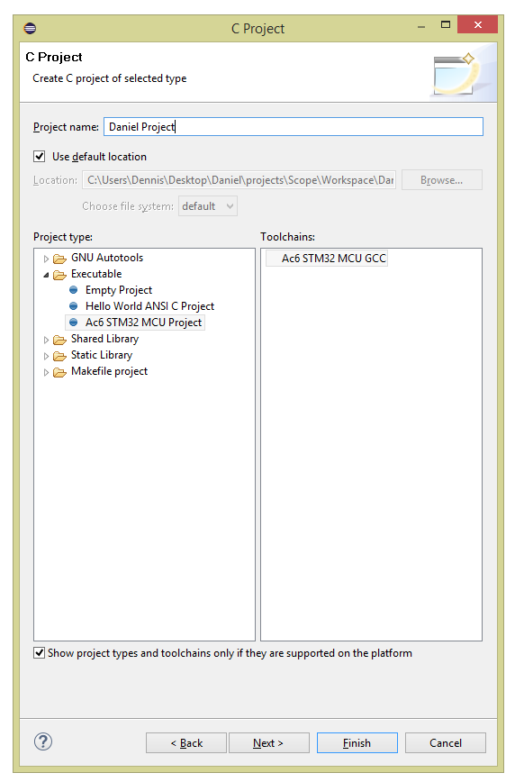
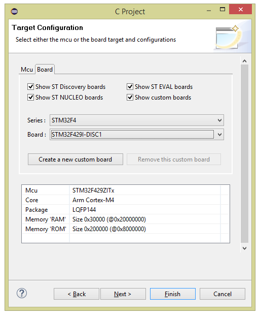
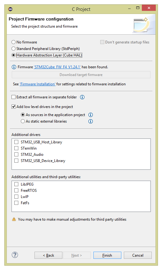
After you’ve got it downloaded and installed, let’s make a new project. Click on File->New->Project and select C Project. If everything installed properly, you should have an option under “Executable” on the left that is Ac6 STM32 MCU Project; select that, give it a name, and hit next and next again on the next screen. When you get to the Target Configuration Screen, select STM32F4 on the Series drop-down and STM32F429I-DISC1 on the Board drop-down and hit Next. Finally, select “Hardware Abstraction Layer (Cube HAL)” in the Project Firmware configuration and hit Finish. This process is detailed in the images below (please click on each of them for the full-sized equivalent).
The Hardware Abstraction Layer libraries are a set of header files that, you guessed it, help you use the hardware built-in to the MCU. The Standard Peripheral Library used to be the de facto standard, and you’ll still see a lot of examples using them out on the web, but they have been deprecated in favor of the HAL libraries, so we will be using those instead.
After completing the above steps, you should have a project folder on the far left screen in Eclipse with the name you typed in. If we open that folder open we’ll see some subfolders of interest:
- Binaries – This holds the file(s) that actually get written to the MCU (called an “.elf” file)
- Includes – Standard C include files
- HAL_Driver – Manuals, include files, and source files for the HAL libraries. We’ll be browsing these a lot.
- src – Your own code
- inc – Your own include files
- Utilities – “Bonus” content, including a folder for the specific eval board we’re using (STM32F429I-Discovery) that has specific header files and source code for how the board is connected (for instance, we can refer to the first LED as LED0 rather than “drive GPIO pin 13 of IO block G”)
- Among others
The HAL files are fairly well documented. For instance, here’s a set of comments detailed how to set up the GPIO in stm32f4xx_hal_gpio.c:
/*
                    ##### How to use this driver #####
  ==============================================================================
  [..]
    (#) Enable the GPIO AHB clock using the following function: __HAL_RCC_GPIOx_CLK_ENABLE().

    (#) Configure the GPIO pin(s) using HAL_GPIO_Init().
        (++) Configure the IO mode using "Mode" member from GPIO_InitTypeDef structure
        (++) Activate Pull-up, Pull-down resistor using "Pull" member from GPIO_InitTypeDef
             structure.
        (++) In case of Output or alternate function mode selection: the speed is
             configured through "Speed" member from GPIO_InitTypeDef structure.
        (++) In alternate mode is selection, the alternate function connected to the IO
             is configured through "Alternate" member from GPIO_InitTypeDef structure.
        (++) Analog mode is required when a pin is to be used as ADC channel
             or DAC output.
        (++) In case of external interrupt/event selection the "Mode" member from
             GPIO_InitTypeDef structure select the type (interrupt or event) and
             the corresponding trigger event (rising or falling or both).

    (#) In case of external interrupt/event mode selection, configure NVIC IRQ priority
        mapped to the EXTI line using HAL_NVIC_SetPriority() and enable it using
        HAL_NVIC_EnableIRQ().

    (#) To get the level of a pin configured in input mode use HAL_GPIO_ReadPin().

    (#) To set/reset the level of a pin configured in output mode use
        HAL_GPIO_WritePin()/HAL_GPIO_TogglePin().

    (#) To lock pin configuration until next reset use HAL_GPIO_LockPin().


    (#) During and just after reset, the alternate functions are not
        active and the GPIO pins are configured in input floating mode (except JTAG
        pins).

    (#) The LSE oscillator pins OSC32_IN and OSC32_OUT can be used as general purpose
        (PC14 and PC15, respectively) when the LSE oscillator is off. The LSE has
        priority over the GPIO function.

    (#) The HSE oscillator pins OSC_IN/OSC_OUT can be used as
        general purpose PH0 and PH1, respectively, when the HSE oscillator is off.
        The HSE has priority over the GPIO function.
*/
Let’s blink an LED!
This is basically the “Hello World” equivalent of embedded systems, so let’s get right to it! First off, let’s take a quick peek at the schematic for the board we’re working with. You’ll see on page 6 that we have two LEDs, one green and one red; the green LED is connected to pin 13 of GPIO bank G (that’s on page 5) through a 510 ohm resistor. The red LED is connected to pin 14 of GPIO bank G through a 680 ohm resistor. For this short example, let’s ignore the fancy “Utilities” libraries and use this information from the schematic. So this is what we need in order to create a successful program:
- Initialize the system clock (we can technically rely on whatever is the default, but let’s try to start off on the right foot).
- Initialize all the HAL stuff and GPIO bank G where the LED is.
- Initialize the pin connected to the LED
- Drive the LED high and low, with a delay in between of, say, half a second.
Here are the includes we will need:
- stm32f4xx.h – General STM32F4 MCU family library
- stm32f429.h – LIbrary more specific to the STM32F429 MCU
- stm32f4xx_hal_gpio.h – GPIO library
- stm32f4xx_hal.h – Another general STM32F4 library, this time specific to HAL
Let’s go ahead and dive into the code for the main function for this quick demo program:
#include "stm32f4xx.h"
#include "stm32f429xx.h"
#include "stm32f4xx_hal_gpio.h"
#include "stm32f4xx_hal.h"

static void SystemClock_Config(void);
void Error_Handler();

int main(void)
{
    // Initialize the hardware abstraction layer libraries
    HAL_Init();

    // Route the clock to GPIO Bank G
    __HAL_RCC_GPIOG_CLK_ENABLE();

    /* Set up the GPIO:
           1. Using pins 13 and 14
           2. Push-pull (rather than open drain)
           3. No pull-down or pull-up
           4. Low frequency (nothing fancy here!)
    */
    GPIO_InitTypeDef g = {GPIO_PIN_13 | GPIO_PIN_14, GPIO_MODE_OUTPUT_PP, GPIO_NOPULL, GPIO_SPEED_FREQ_LOW};
    HAL_GPIO_Init(GPIOG, &g);

    /* Configure the system clock to 180 MHz */
    SystemClock_Config();

    while (1) {
        // Blink the green LED and wait 500ms
        HAL_GPIO_TogglePin(GPIOG, GPIO_PIN_13);
        HAL_Delay(500);
    }
}
As we talked about before, the code above pretty obviously initializes the HAL modules, the GPIO bank we want (bank G), sets up the system clock, and starts blinking the LED. Let’s dig into the GPIO_InitTypeDef structure a little more. The ST Micro libraries follow this module very closely everywhere as far as I can tell – the module is initialized by passing a initialization function a pointer to a structure with all the relavant bits (pun fully intended) you want initialized. In this case, the structure is defined in TODO and reproduced below:
/**
  * @brief GPIO Init structure definition
  */
typedef struct
{
  uint32_t Pin;       /*!< Specifies the GPIO pins to be configured.
                           This parameter can be any value of @ref GPIO_pins_define */

  uint32_t Mode;      /*!< Specifies the operating mode for the selected pins.
                           This parameter can be a value of @ref GPIO_mode_define */

  uint32_t Pull;      /*!< Specifies the Pull-up or Pull-Down activation for the selected pins.
                           This parameter can be a value of @ref GPIO_pull_define */

  uint32_t Speed;     /*!< Specifies the speed for the selected pins.
                           This parameter can be a value of @ref GPIO_speed_define */

  uint32_t Alternate;  /*!< Peripheral to be connected to the selected pins.
                            This parameter can be a value of @ref GPIO_Alternate_function_selection */
}GPIO_InitTypeDef;

// And here's the #defines we can use with the above!

/** @defgroup GPIO_pins_define GPIO pins define
  * @{
  */
#define GPIO_PIN_0                 ((uint16_t)0x0001)  /* Pin 0 selected    */
#define GPIO_PIN_1                 ((uint16_t)0x0002)  /* Pin 1 selected    */
#define GPIO_PIN_2                 ((uint16_t)0x0004)  /* Pin 2 selected    */
#define GPIO_PIN_3                 ((uint16_t)0x0008)  /* Pin 3 selected    */
#define GPIO_PIN_4                 ((uint16_t)0x0010)  /* Pin 4 selected    */
#define GPIO_PIN_5                 ((uint16_t)0x0020)  /* Pin 5 selected    */
#define GPIO_PIN_6                 ((uint16_t)0x0040)  /* Pin 6 selected    */
#define GPIO_PIN_7                 ((uint16_t)0x0080)  /* Pin 7 selected    */
#define GPIO_PIN_8                 ((uint16_t)0x0100)  /* Pin 8 selected    */
#define GPIO_PIN_9                 ((uint16_t)0x0200)  /* Pin 9 selected    */
#define GPIO_PIN_10                ((uint16_t)0x0400)  /* Pin 10 selected   */
#define GPIO_PIN_11                ((uint16_t)0x0800)  /* Pin 11 selected   */
#define GPIO_PIN_12                ((uint16_t)0x1000)  /* Pin 12 selected   */
#define GPIO_PIN_13                ((uint16_t)0x2000)  /* Pin 13 selected   */
#define GPIO_PIN_14                ((uint16_t)0x4000)  /* Pin 14 selected   */
#define GPIO_PIN_15                ((uint16_t)0x8000)  /* Pin 15 selected   */
#define GPIO_PIN_All               ((uint16_t)0xFFFF)  /* All pins selected */
/**
  * @}
  */

/** @defgroup GPIO_mode_define GPIO mode define
  * @brief GPIO Configuration Mode
  *        Elements values convention: 0xX0yz00YZ
  *           - X  : GPIO mode or EXTI Mode
  *           - y  : External IT or Event trigger detection
  *           - z  : IO configuration on External IT or Event
  *           - Y  : Output type (Push Pull or Open Drain)
  *           - Z  : IO Direction mode (Input, Output, Alternate or Analog)
  * @{
  */
#define  GPIO_MODE_INPUT                        0x00000000U   /*!< Input Floating Mode                   */
#define  GPIO_MODE_OUTPUT_PP                    0x00000001U   /*!< Output Push Pull Mode                 */
#define  GPIO_MODE_OUTPUT_OD                    0x00000011U   /*!< Output Open Drain Mode                */
#define  GPIO_MODE_AF_PP                        0x00000002U   /*!< Alternate Function Push Pull Mode     */
#define  GPIO_MODE_AF_OD                        0x00000012U   /*!< Alternate Function Open Drain Mode    */

#define  GPIO_MODE_ANALOG                       0x00000003U   /*!< Analog Mode  */

#define  GPIO_MODE_IT_RISING                    0x10110000U   /*!< External Interrupt Mode with Rising edge trigger detection          */
#define  GPIO_MODE_IT_FALLING                   0x10210000U   /*!< External Interrupt Mode with Falling edge trigger detection         */
#define  GPIO_MODE_IT_RISING_FALLING            0x10310000U   /*!< External Interrupt Mode with Rising/Falling edge trigger detection  */

#define  GPIO_MODE_EVT_RISING                   0x10120000U   /*!< External Event Mode with Rising edge trigger detection               */
#define  GPIO_MODE_EVT_FALLING                  0x10220000U   /*!< External Event Mode with Falling edge trigger detection              */
#define  GPIO_MODE_EVT_RISING_FALLING           0x10320000U   /*!< External Event Mode with Rising/Falling edge trigger detection       */
/**
  * @}
  */
/** @defgroup GPIO_speed_define  GPIO speed define
  * @brief GPIO Output Maximum frequency
  * @{
  */
#define  GPIO_SPEED_FREQ_LOW         0x00000000U  /*!< IO works at 2 MHz, please refer to the product datasheet */
#define  GPIO_SPEED_FREQ_MEDIUM      0x00000001U  /*!< range 12,5 MHz to 50 MHz, please refer to the product datasheet */
#define  GPIO_SPEED_FREQ_HIGH        0x00000002U  /*!< range 25 MHz to 100 MHz, please refer to the product datasheet  */
#define  GPIO_SPEED_FREQ_VERY_HIGH   0x00000003U  /*!< range 50 MHz to 200 MHz, please refer to the product datasheet  */
/**
  * @}
  */

 /** @defgroup GPIO_pull_define GPIO pull define
   * @brief GPIO Pull-Up or Pull-Down Activation
   * @{
   */
#define  GPIO_NOPULL        0x00000000U   /*!< No Pull-up or Pull-down activation  */
#define  GPIO_PULLUP        0x00000001U   /*!< Pull-up activation                  */
#define  GPIO_PULLDOWN      0x00000002U   /*!< Pull-down activation                */
/**
  * @}
  */
The code uses two helper functions, static void SystemClock_Config(void) (sets up the system clock) and void Error_Handler() (acts on errors on initialization of the system clock). Unfortunately, since we can’t do a print or anything like that, all the error handler will do for now is turn on the red LED and hang the program. Here’s the code for this:
/**
  * @brief  System Clock Configuration
  *         The system Clock is configured as follow :
  *            System Clock source            = PLL (HSE)
  *            SYSCLK(Hz)                     = 180000000
  *            HCLK(Hz)                       = 180000000
  *            AHB Prescaler                  = 1
  *            APB1 Prescaler                 = 4
  *            APB2 Prescaler                 = 2
  *            HSE Frequency(Hz)              = 8000000
  *            PLL_M                          = 8
  *            PLL_N                          = 360
  *            PLL_P                          = 2
  *            PLL_Q                          = 7
  *            VDD(V)                         = 3.3
  *            Main regulator output voltage  = Scale1 mode
  *            Flash Latency(WS)              = 5
  * @param  None
  * @retval None
  */
static void SystemClock_Config(void)
{
  RCC_ClkInitTypeDef RCC_ClkInitStruct;
  RCC_OscInitTypeDef RCC_OscInitStruct;

  /* Enable Power Control clock */
  __HAL_RCC_PWR_CLK_ENABLE();

  /* The voltage scaling allows optimizing the power consumption when the device is
     clocked below the maximum system frequency, to update the voltage scaling value
     regarding system frequency refer to product datasheet.  */
  __HAL_PWR_VOLTAGESCALING_CONFIG(PWR_REGULATOR_VOLTAGE_SCALE1);

  /* Enable HSE Oscillator and activate PLL with HSE as source */
  RCC_OscInitStruct.OscillatorType = RCC_OSCILLATORTYPE_HSE;
  RCC_OscInitStruct.HSEState = RCC_HSE_ON;
  RCC_OscInitStruct.PLL.PLLState = RCC_PLL_ON;
  RCC_OscInitStruct.PLL.PLLSource = RCC_PLLSOURCE_HSE;
  RCC_OscInitStruct.PLL.PLLM = 8;
  RCC_OscInitStruct.PLL.PLLN = 360;
  RCC_OscInitStruct.PLL.PLLP = RCC_PLLP_DIV2;
  RCC_OscInitStruct.PLL.PLLQ = 7;
  if(HAL_RCC_OscConfig(&RCC_OscInitStruct) != HAL_OK)
  {
    Error_Handler();
  }

  /* Activate the Over-Drive mode */
  HAL_PWREx_EnableOverDrive();

  /* Select PLL as system clock source and configure the HCLK, PCLK1 and PCLK2
     clocks dividers */
  RCC_ClkInitStruct.ClockType = (RCC_CLOCKTYPE_SYSCLK | RCC_CLOCKTYPE_HCLK | RCC_CLOCKTYPE_PCLK1 | RCC_CLOCKTYPE_PCLK2);
  RCC_ClkInitStruct.SYSCLKSource = RCC_SYSCLKSOURCE_PLLCLK;
  RCC_ClkInitStruct.AHBCLKDivider = RCC_SYSCLK_DIV1;
  RCC_ClkInitStruct.APB1CLKDivider = RCC_HCLK_DIV4;
  RCC_ClkInitStruct.APB2CLKDivider = RCC_HCLK_DIV2;
  if(HAL_RCC_ClockConfig(&RCC_ClkInitStruct, FLASH_LATENCY_5) != HAL_OK)
  {
    Error_Handler();
  }
}

void Error_Handler() {
    // Oops. Bad stuff happened! Let's turn on the red LED.
    HAL_GPIO_WritePin(GPIOG, GPIO_PIN_13, GPIO_PIN_SET);

    while (1) { }
}
Don’t worry too much about SystemClock_Config(void) yet – it’s a copy-pasted version of ST’s standard clock configuration function for running the system at 180 MHz. We obviously don’t need to run the processor at it’s maximum clock for blinking an LED, but we’ll likely end up running it at this frequency in the finished product. We will dive more deeply into how that code gets generated inside the STM32F4CubeMX software in a few posts.
That’s it for this post! After you put the code above in one file (main.c) and build (using the hammer icon), you can program the board by right clicking on the project (the folder) and selecting Target -> Program Chip. You can tell the IDE to reset the board and you should see the green LED start blinking right away like in the below animation!
See you next time for some fun running the demos ST Micro includes with their libraries on this evaluation board and another short example!.