Today we’ll continue to play with the STM32F429-DISC1 eval board to learn more about the MCU and what it can do.
What’s an interrupt?
If your childhood was anything like like mine, your parents probably reprimanded you whenever you interrupted someone while they were talking. And if you were anything like me, you were interrupting because something occurred to you (likely as a response to whatever was being said by the interrupted person) and you wanted to say it before you forgot what it was, or maybe before it lost its impact.
Like us humans, the processor inside an MCU is in an environment with lots of action going on around it – buttons connected to it are being pressed, samples are coming in from an ADC, memory is filling up, timers are going off, and all sorts of other things are happening. There are two common ways of dealing with all this action – let’s review them real quick.
One approach, which as you’ll recall we used on the nixie clock project and is described here, is called polling. In a polling architecture, the processor checks on its subsystems “once in a while” to see what happened; the processor will set its own “checking periods” and is responsible for spending that time looking at each subsystem to see if it has anything to report to it. Some subsystems will have flags (bits that are set or cleared) that tell the processor that something happened since the last time that it checked; the error counters inside of Ethernet PHY chips are good examples of this – many error counters are self-clearing and the processor is expected to check them every once in a while. Other subsystems are not this smart – GPIO pins connected to buttons are either high or low, and if you’re not polling quickly enough you might just miss something that happened (e.g. you may only register one button press if there were two quick button presses in succession). Polling has fallen out of favor because, although it is simpler from an architecture, “wrapping your head around it” point of view, it is also more processor intensive. This is because the processor can’t be in “sleep mode” as much, as it has to constantly be waking itself up to check all the subsystems. In a battery-powered product, for example, you’d ideally like the processor to be asleep as much as possible, waking up only when absolutely necessary to deal with something that’s happened (like a button press).
This is where the second approach comes in, and that’s interrupts. Most processors have an interrupt controller built in to it, and that interrupt controller is connected to a wide variety of interrupt sources (both internal and external to the MCU). Here’s some examples:
- GPIO pins connected to external devices (control signals, buttons/keypads, etc.)
- Internal timers that can be configured to generate an interrupt every so often
- Specific bits inside of registers that indicate various states for internal subsystems (e.g. a “half-full flag” inside a FIFO memory telling you that it’s now half full, a “link bit” inside an Ethernet PHY that tells you that a cable was plugged-in, an “enumeration complete” bit inside a USB or PCIe controller register that tells you a new device was hooked-up)
- And more!
You have to write code to set up the interrupts – this means you want the interrupt controller to pay attention to the interrupts you specify in particular (the controller will typically ignore all sources by default). You can configure specific details about the interrupt source – like whether you want it to interrupt when the GPIO pin goes high only, or low only, or both when it goes high and low (for an edge-triggered interrupt). Then you register an interrupt handler function, which is the function that gets called whenever an interrupt of that type is received. Finally, you assign a priority to the interrupt – this is important because some interrupts will fire when you’re halfway through dealing with an interrupt, and in some cases you want to set that aside for a moment, deal with the new interrupt first, and come back to the old interrupt. And in other cases you most certainly do not want to do that.
Here’s a short example of why the priority is important. Let’s say we have two interrupt sources, one is connected to GPIO pin 0 of bank A, which is a push-button, and the other is an internal timer which we configured to fire every 10 ms to keep track of time. The interrupt handler for the button increments a variable in the code which represents how may times the button has been pushed. The interrupt handler for the timer adds 10ms to a variable which represents a supposedly accurate counter of how long it has been since the program started. The board has a display which shows both the time since the program started and the button-press counter. In this simple example, we’d like to have the timer interrupt have higher priority than the button interrupt because we’d like the time variable to be as accurate as possible. It doesn’t hurt anything if it takes a few extra milliseconds to update the button counter because the program was in the middle of doing that when the timer interrupt arrived. However, if we wait for the button interrupt to finish first (if they have equal priorities or if the timer priority is lower), then we’ll have an inaccurate time variable for the rest of the program’s length!
The important thing to keep in mind with interrupts is that we’re handing over the control of when the code gets called to the processor. When we write code for a polling-based architecture, we know exactly when and how often each subsystem gets polled (as a consequence, we might be responsible for writing the code poorly so we end up missing some events, but we still know when the checks happen). With interrupts, we write code that ends up looking a little more disjointed – instead of our main loop being a step-by-step procedure where we, for example, check a button, increment at timer variable, and write these two to the display, all we do in it is write the variables to the display and call it good; instead, somewhere else in the code there’s these two functions that look like they never get called from the main loop but are responsible for incrementing the variables. The processor is then responsible for bringing these two pieces of code together so that they do what we want them to do. Priority, masking, and some other things that we set up at the beginning of the program tells the processor how to do so to get the behavior that we want from the program.
A simple example
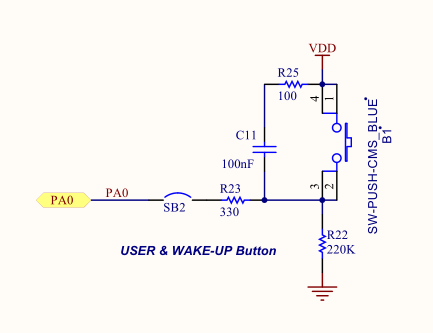
In this example we’ll set up an interrupt on the eval board’s blue push-button switch (the black one is a reset button, so we can’t use it in the code) that will toggle the LED on and off. Here’s the schematic for it:

Note that the button is already debounced in hardware (via R25, C11, and R23) and the signal goes high when the button is pushed. It is connected to pin 0 of GPIO bank A. You’ll remember from the previous post that the green LED is connected to pin 13 of GPIO bank G. So here’s what we have to do to get the behavior we want:
- Initialize GPIO bank G as we did before (to output on both the green and red LED)
- Write an interrupt handler that toggles the LED pin (that’s all it has to do, ST’s code deals with clearing the interrupt and all the other “gritty embedded stuff” for you)
- Initialize GPIO bank as an input with interrupt capability on pin 0. We’ll set it up so it’s edge-triggered when the signal transitions from low to high. The priority can be almost anything since it’s the only interrupt we’ll write; let’s keep it low to make sure nothing else breaks. Finally, we have to tell the processor that the function we wrote above is the interrupt handler for this interrupt.
- That’s it! The while loop can just be an infinite loop that does nothing so that the program keeps running rather than just ending.
You can go ahead and write a program like we did in part 3 of the series. You can copy the clock configuration (SystemClock_Config) and error handler (Error_Handler) functions from there. Here’s our main loop, which will be very similar to the one from that post:
#include "stm32f4xx.h"
#include "stm32f429xx.h"
#include "stm32f4xx_hal_gpio.h"
#include "stm32f4xx_hal.h"
#include "stm32f4xx_hal_exti.h"
#include "stm32f4xx_it.h"

static void SystemClock_Config(void);
static void Error_Handler(void);
static void EXTILine0_Config(void);

int main(void)
{
    // Initialize the hardware abstraction layer libraries
    HAL_Init();
    __HAL_RCC_GPIOG_CLK_ENABLE();

    GPIO_InitTypeDef g = {GPIO_PIN_13 | GPIO_PIN_14, GPIO_MODE_OUTPUT_PP, GPIO_NOPULL, GPIO_SPEED_FREQ_LOW};
    HAL_GPIO_Init(GPIOG, &g);

    /* Configure the system clock to 180 MHz */
    SystemClock_Config();

    /* Configure EXTI Line0 (connected to PA0 pin) in interrupt mode */
    EXTILine0_Config();

    while (1) {

    }
}
Note that the main difference is that we now have a EXTILine0_Config() function which will configure an external interrupt (I guess that’s what “EXTI” is) on line 0 (the button) of GPIO bank A. That looks like this:
/**
  * @brief  Configures EXTI Line0 (connected to PA0 pin) in interrupt mode
  * @param  None
  * @retval None
  */
static void EXTILine0_Config(void)
{
  GPIO_InitTypeDef   GPIO_InitStructure;

  /* Enable GPIOA clock */
  __HAL_RCC_GPIOA_CLK_ENABLE();

  /* Configure PA0 pin as input floating */
  GPIO_InitStructure.Mode = GPIO_MODE_IT_RISING;
  GPIO_InitStructure.Pull = GPIO_NOPULL;
  GPIO_InitStructure.Pin = GPIO_PIN_0;
  HAL_GPIO_Init(GPIOA, &GPIO_InitStructure);

  /* Set EXTI Line0 Interrupt to the lowest priority and enable the interrupt */
  HAL_NVIC_SetPriority(EXTI0_IRQn, 2, 0);
  HAL_NVIC_EnableIRQ(EXTI0_IRQn);
}
A lot of this looks the same as the GPIO bank G initialization. Note that the “mode” parameter of the structure is now set to GPIO_MODE_IT_RISING, which will be an input that issues an interrupt on a rising edge. Finally, we set the priority to 2 (on a scale from 0 to 15, where 0 and 1 are really low priority events we shouldn’t mess with) and the subpriority to 0 (I’m not sure what that is yet, if we’re being honest), and the interrupt (often shortened to “IRQ”) is enabled. A few other things to note – internally, all the GPIO banks are connected together, so that all pin 0s (of bank A, bank B, all the way to bank G) can only issue EXTI0_IRQn interrupts. That’s something we’re going to have to keep in mind. That’s why pin 0 of bank A (the one that the button is connected to) corresponds to EXTI0_IRQn. It also means that ST has configured the code to have a specific interrupt handler already – EXTI0_IRQn has the interrupt handler function HAL_GPIO_EXTI_Callback automatically registered to it, so we don’t have to do anything except write this function, which I reproduced below. Since there’s only one interrupt handler for all EXTI events (i.e. EXTI0-EXTI15), the function has an argument which indicates which pin(s) triggered the interrupt. In this case, all we have to do with that is check that it corresponds to the pin to which the button is connected (GPIO_PIN_0):
/**
  * @brief EXTI line detection callbacks
  * @param GPIO_Pin: Specifies the pins connected EXTI line
  * @retval None
  */
void HAL_GPIO_EXTI_Callback(uint16_t GPIO_Pin)
{
    if (GPIO_Pin == GPIO_PIN_0) {
        HAL_GPIO_TogglePin(GPIOG, GPIO_PIN_13);
    }
}
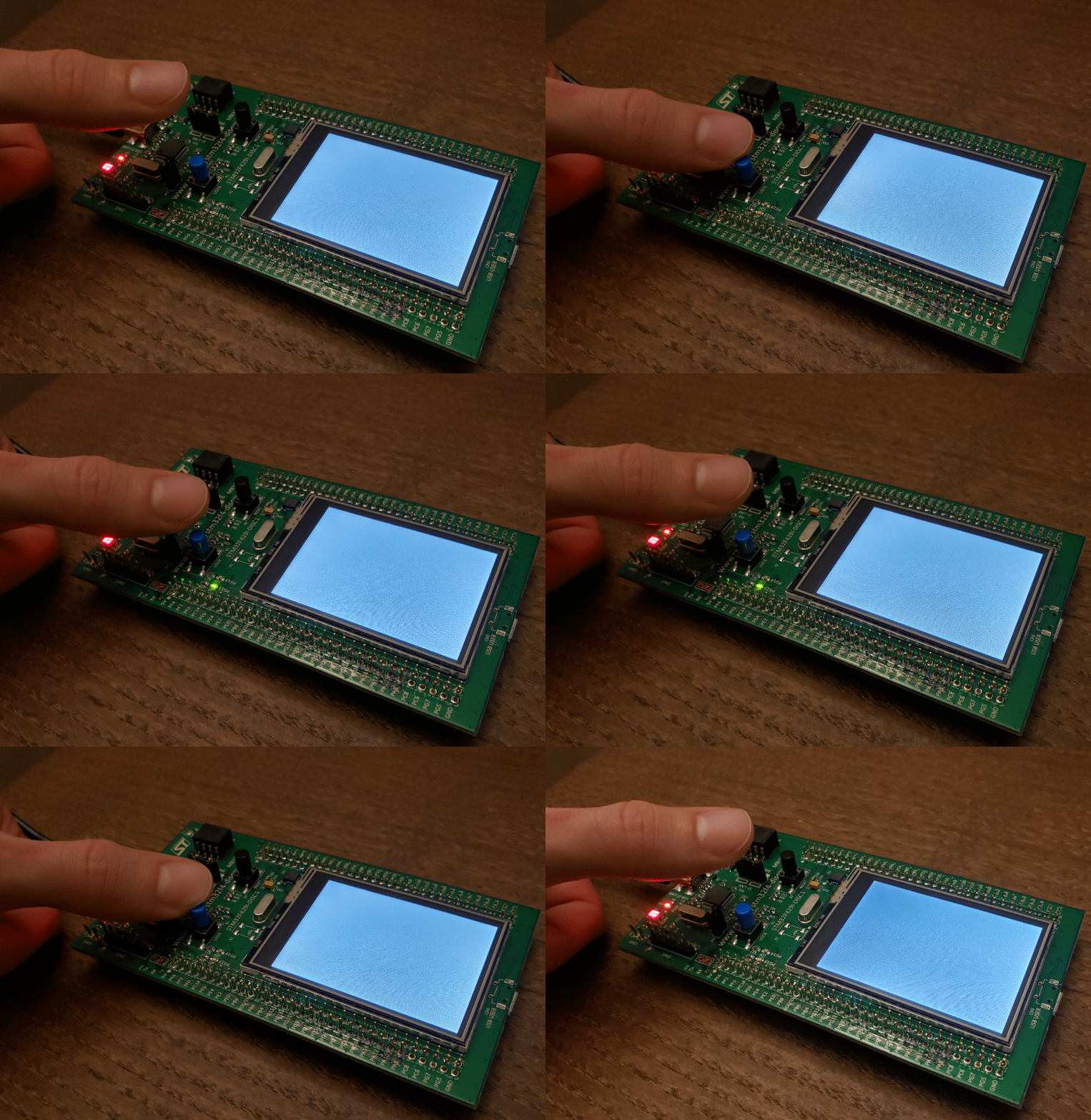
That should be all there is to it! You can build and run the program like we did in part 3 of the series, and you should see behavior like this:

