")
Hi all! Let’s get this blog started!
I have a Raspberry Pi 3 that was sitting around most of the time, so I recently started working on a Raspberry Pi powered nixie tube clock. It’s a pretty basic project and I’m not quite done yet, but I’ve already run into several snags, some which are only natural since I didn’t have any experience with CAD (and I didn’t own a pair of calipers…) and others which I’m a little more embarrassed to admit. Let’s get into it!
Concept
I want to make a simple six digit (HH:MM:SS, no colons) clock, with one tube per digit. The Raspberry Pi can get the time from the internet (through WiFi so there’s no need to support an Ethernet cable going into the enclosure), and maybe display some home statistics from bluetooth sensors that I can scatter around the house (temperature and humidity come to mind). These statistics should be stored on the RPi’s SD card so that I can later retrieve them through SFTP for further processing (e.g. graphing). I’d like to have a single button which I can press to cycle through time, indoor temperature, outdoor temperature, and humidity. Lastly, I’d like it to have a PIR motion sensor for turning on the clock only when someone is present (to preserve the tubes, since their lifetime appears to be in thousands of hours). Since I’ve never used CAD for any kind of mechanical design, I want to challenge myself to design and 3D print (or otherwise manufacture) an enclosure. It doesn’t have to be anything fancy, it can just be a box that holds the boards, has cutouts for the button and the tubes, and doesn’t rattle or fall apart when it’s all put together. It is by embracing low standards that we arrive at success, but, at the end of the day, I may very well be looking at this thing every day, so I don’t want it to be too ugly.

Circuit
For the uninitiated, nixie tubes are gas discharge tubes (GDTs) which work in a similar fashion to a neon sign: a high voltage is used to ionize a noble gas inside of the tube, making it glow a bright color. There are metal pieces (cathodes) bent to look like digits that are at a high voltage, causing the glowing ionized gas to crowd around the digit and make light in the shape of that digit. From a circuit point of view, nixie tubes work more or less like LEDs – the anode is connected to a high voltage (in this case quite high – 160V or more) and the cathode corresponding to the digit you want displayed is grounded, with a series resistor somewhere in there to limit the current to around 3mA. Although the nixie tube requires 160V to light, once it is on it will drop less voltage, typically around 130V.
From that description, here’s the basic building blocks that we need:
- A boost converter from 5V (from the Pi) to 170V. I found an open hardware design (and more nixie tube resources) on SURFNCIRCUITS, so I ordered some of his boards and assembled one myself.
- 60 (!) GPIOs to control the digits (10 digits, 0-9, for six tubes). I decided to use a 1 of 10 BCD (binary coded decimal) decoder to convert 4 control lines into ten lines. That gets me to 24 GPIOs, which I have on my RPi. This could be reduced further by multiplexing the display quickly so as to only drive 1 tube at a time, but I didn’t pursue that.
- A way to drive the cathodes to ground. A popular solution seems to use old Russian chips that were meant to do exactly this (drive nixie tube digits, e.g. the 74141), but I settled on using 30 dual NPN MMDTA42 high voltage BJTs since the Russian chips are tricky to find.
Here’s a snapshot of what we have from the above from a schematics point of view (for each nixie tube):
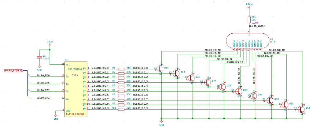
Schematic snip for single nixie tube
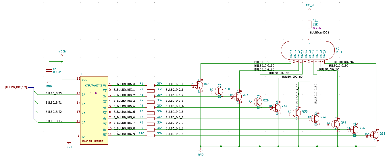
Here’s where the first mistake comes in. You’ll notice that the 74HC42’s output pins are inverted, so the logic table is as follows:
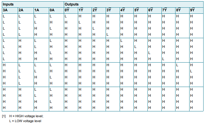
Notably, no matter what input you put in, all the chip will do is ensure that only one output is low! This is the opposite of what we’d like for driving NPN transistors! I somehow (didn’t think very hard) convinced myself I could just fix this in software by inverting bits, but this is clearly not the case…Consequently, I have swapped the chip for Nexperia’s HEF4028BT, which has only one bit high all the time (noninverting outputs). Unfortunately, the pinout is a little different, so I’ll have to re-spin my boards (or suffer a lot of rework), but that’s how it goes!
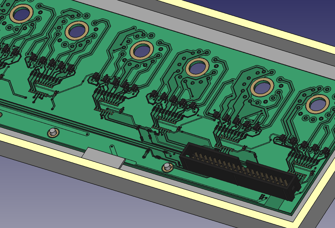
There’s a couple of other missteps that have more than convinced me to re-spin the board. Firstly, the nixie tubes are upside-down. You can sort of tell this is the case if you stare at the picture of the board with the tube on it. Additionally, the location of the fourth pin on the footprint is a little off; you can force the tube in there, but it really bends that lead. I considered mounting the board upside-down and clipping that lead (and connecting through a blob of solder), but the 74HC42 blunder really sealed the deal on getting a new board.
In my defense, the only resource I could find on the footprint of this tube was this diagram, which, well…leaves one wanting. And I double checked my math on that fourth pin and I still think I did it right, so, who knows! For the new board I’ll use Mark Smith’s footprint from SURFNCIRCUITS since I know he’s actually built IN-4 nixie tube clocks.
The good thing about redesigning the board is that I’ve had more time to think about what I’d like from this project since the first spin. I’ve added the button and PIR sensor requirements, and now I’m also thinking of arranging the digits in a more creative way, perhaps slanted in 45 degree angles. Because I’m taking my time with this project, I don’t really mind the delay.
That’s all I have for today, so here’s a couple of galleries of the debug and enclosure design processes!
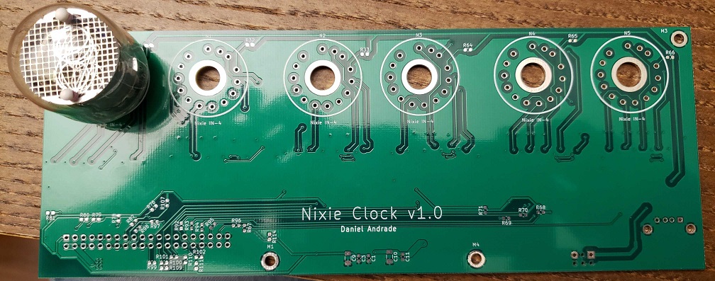
First boards that arrived in July 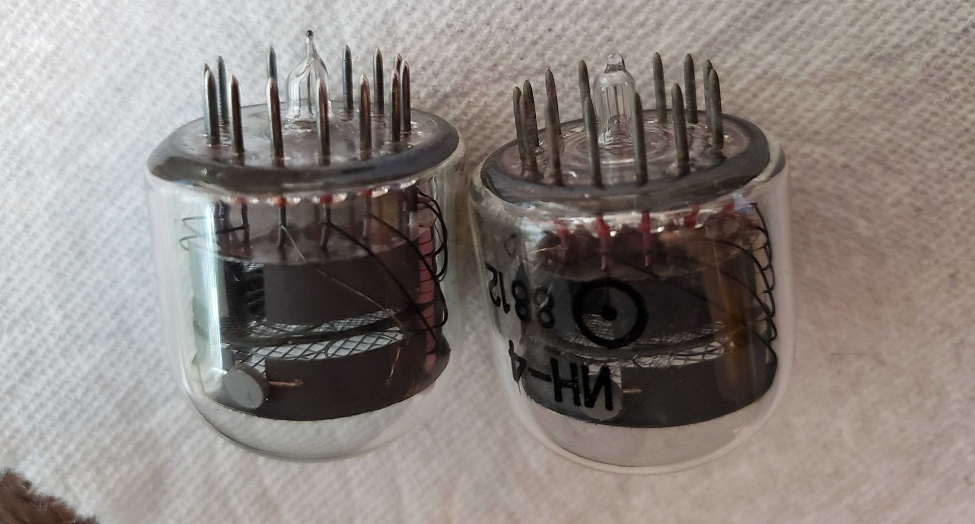
Removing 40+ years of oxidation on the nixie tube leads (compare left to right) 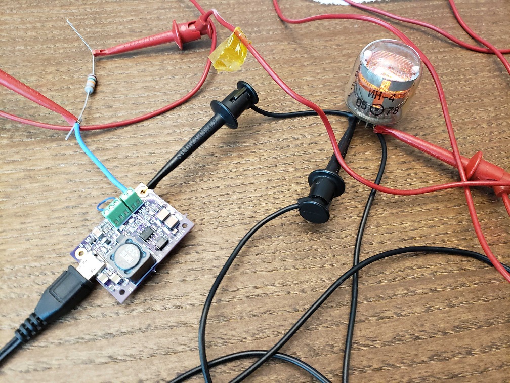
Testing out the nixie tubes when they first arrived 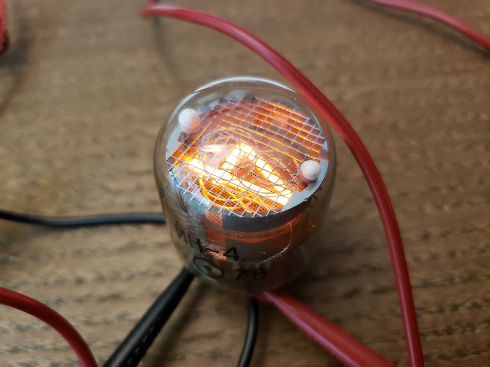
First time seeing a digit on a nixie tube!
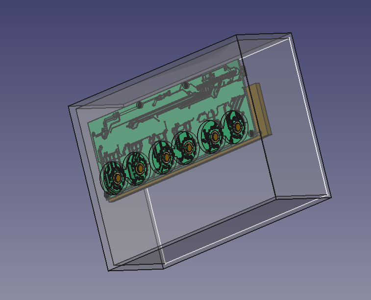
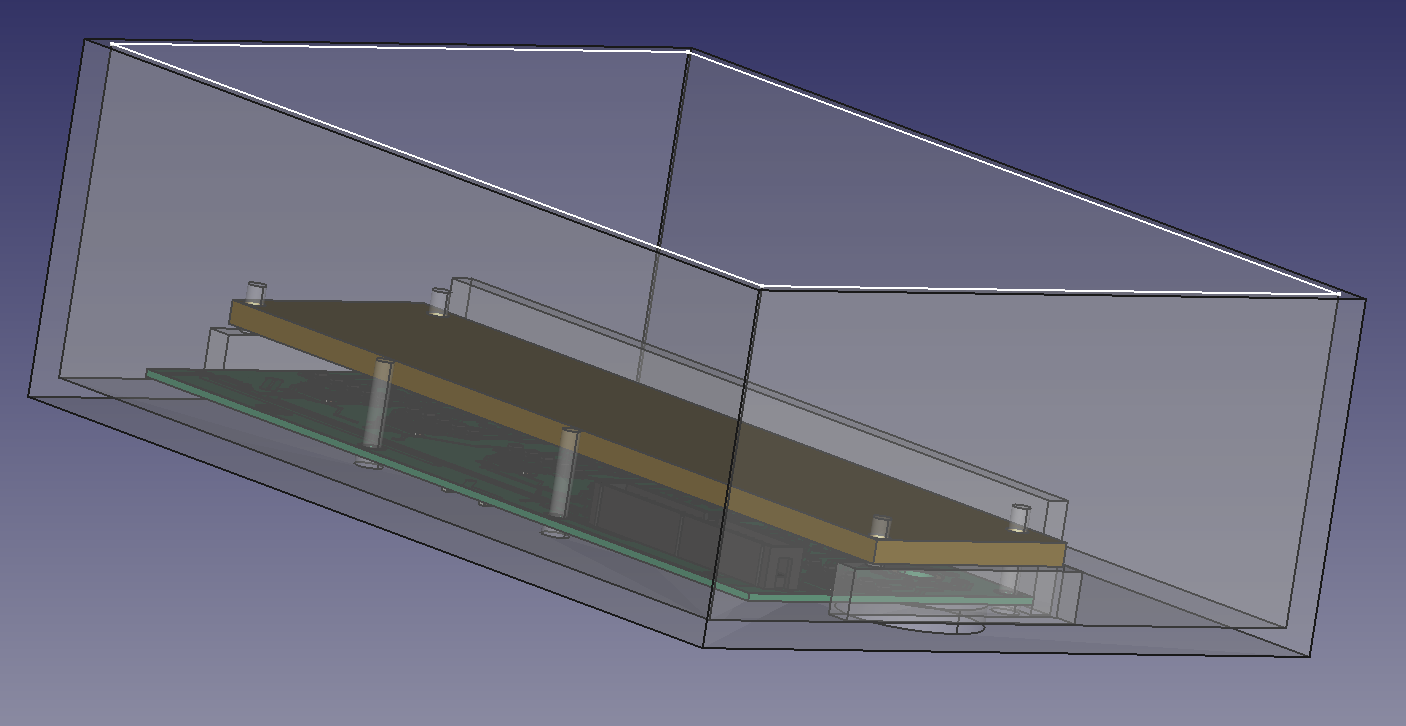
Front view 
Side view 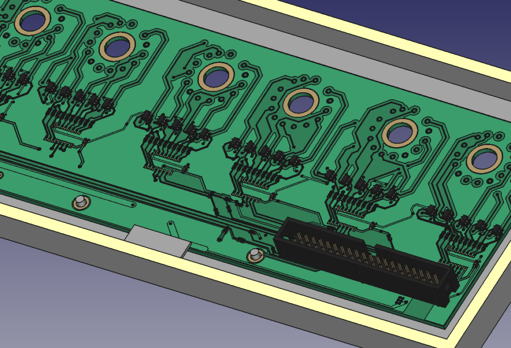
Check out the detail that KiCAD brings into FreeCAD!