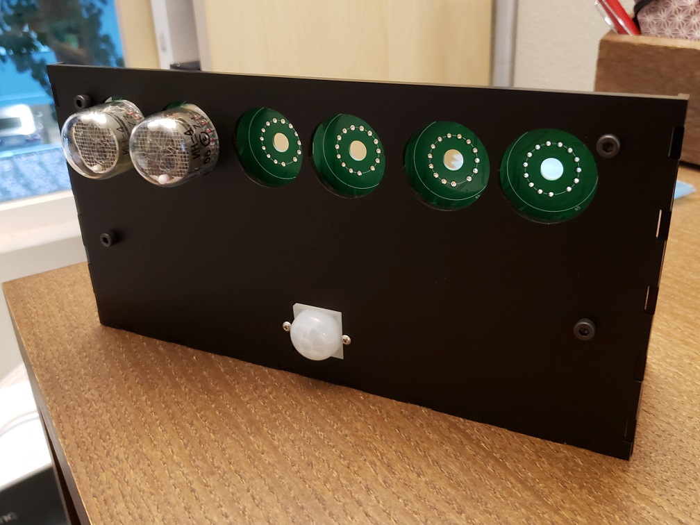
We did it, folks! It’s at least functional, which is more than I can say for a lot of my own personal projects that I’ve started! I’ll even dare to say that I think this even looks better than the inspirational picture I posted on my first post!
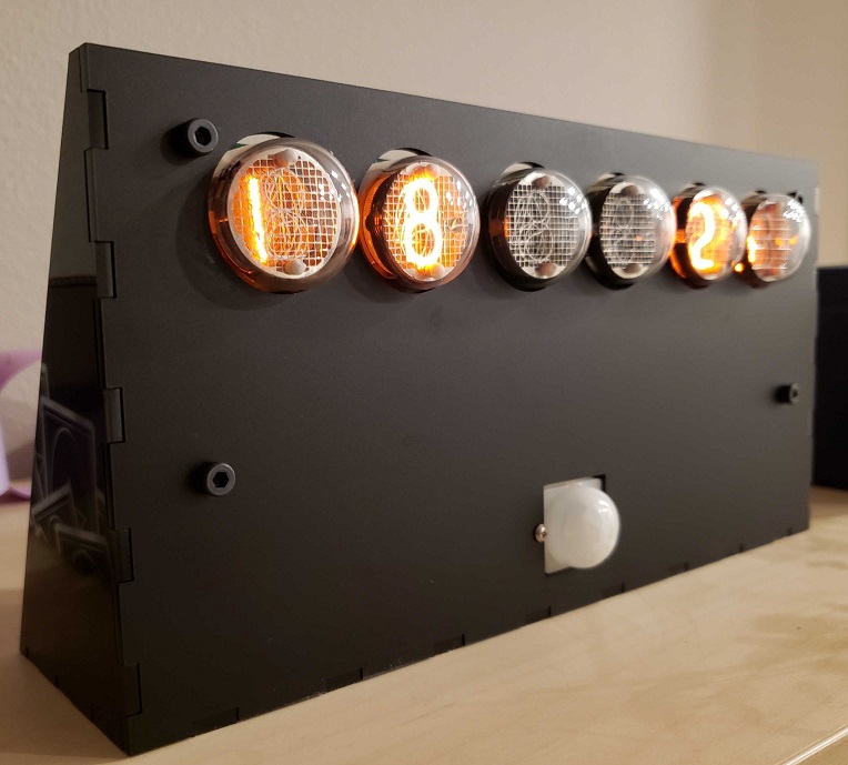
The clock from an odd angle
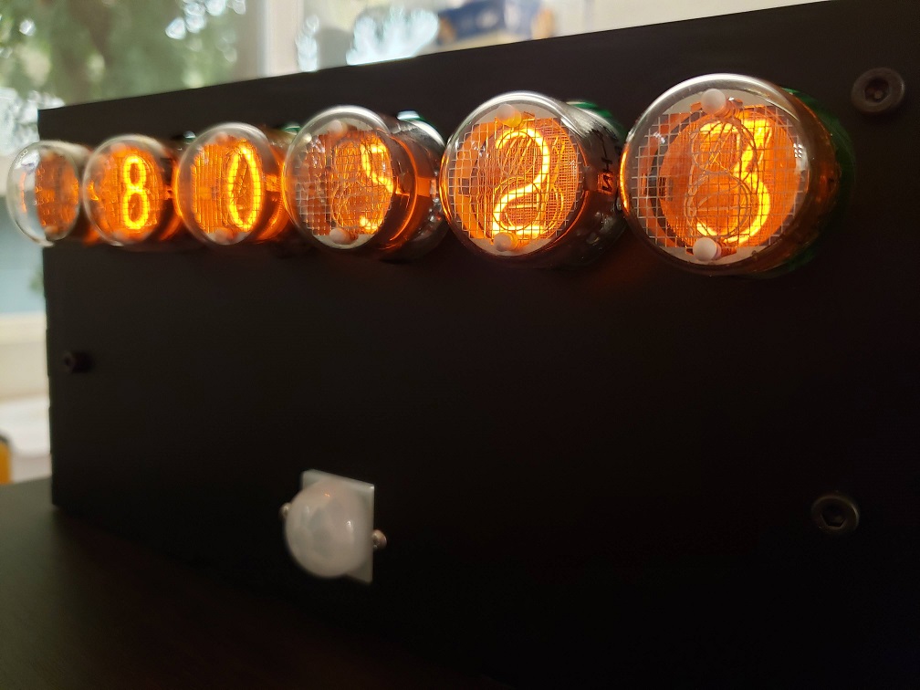
The full enclosure, with the tubes recessed a little bit more using 20mm standoffs
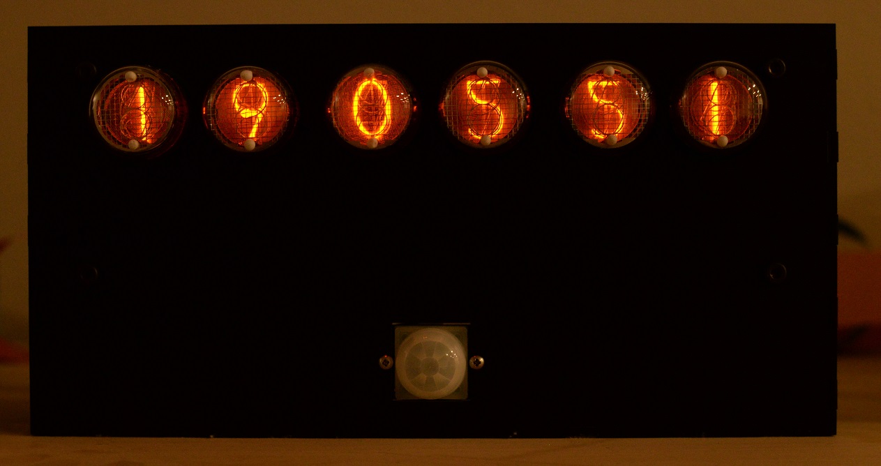
Finished clock showing the time (dark image so you can better see the glow of the tubes)
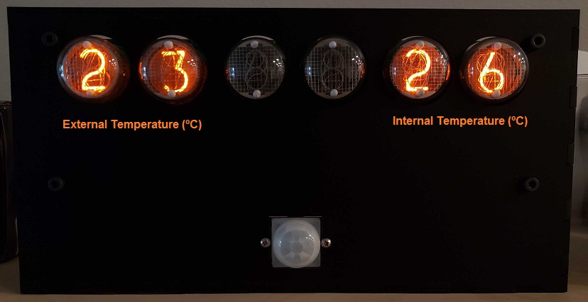
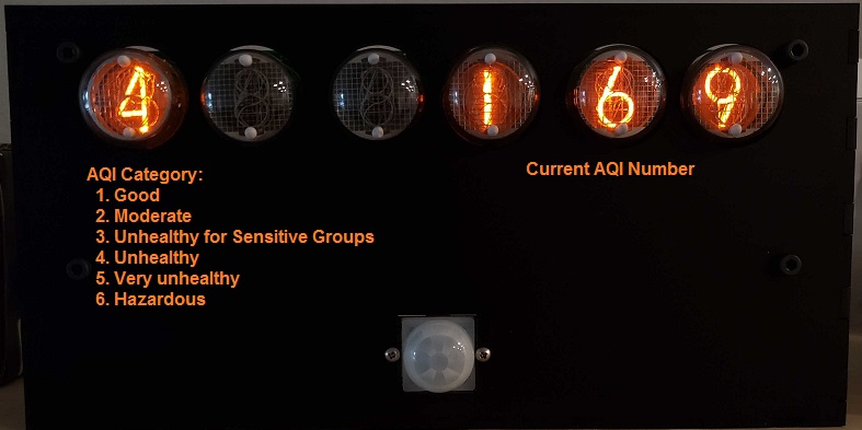
The clock shows the time, the internal temperature, the external temperature (based on querying OpenWeatherMap API with the right city code), and the AQI (air quality index using the AirNow API – a good idea for us in the west coast of the US who happen to be experiencing a lot of smoke in the air!). Right now I’ve got it alternating between the time, the internal and external temperatures (in one screen), and the AQI. The temperature units can be set to Celsius or Fahrenheit. Right now I cycle between these three “screens” every 20 seconds.
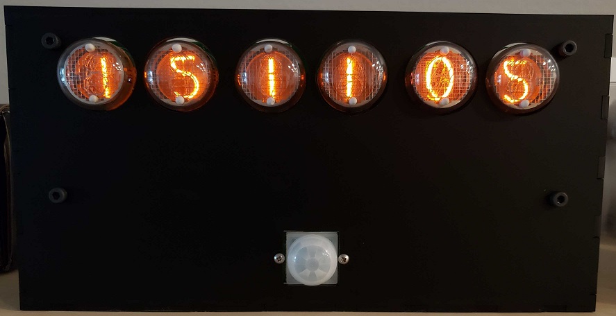
Time (HHMMSS)
Temperatures
AQI (there was smoke this day!)
The PIR sensor is working well, too! I tuned the time it would have to go without seeing motion to fall asleep to a minute; this seems to work well because it’s enough time to cycle through all three screens and because I put the clock in a rather central location where it’s easy to wake it up by waving at it. The sensor has a 7m range in a 120 degree cone, which turns out to be just about perfect. I was having issues making it work initially and then I realized that I was giving it a 3.3V supply when it wanted to be connected to 5V – oops! In my defense, it specs 3-5V on the Adafruit website, but then there’s a little bit of text saying that if you want lower voltages to work you have to bypass the regulator on the PIR sensor board which I completely missed. It was easier to connect it directly to 5V instead, so I went ahead and changed the wiring to make that work. I’ll clean up the code a little bit more, edit my code post from last week, and post it there.
The project is more or less “done” now, but I’ll do a couple more review posts where we’ll look at reducing the cost of the whole product as well as making it easier to put together. Specifically, I’d like to:
Improve the nixie footprints by rotating them clockwise slightly and make all of the holes significantly larger; this should allow the person soldering the tubes to rotate them in position and then solder them.
Move the power supply onto the main board
Remove the 40pin ribbon cable and allow a RPi Zero W to be directly connected instead (via a 90 degree header). Margaret has one that I can try to make sure it works OK (I can’t think of why it wouldn’t)
Clean up and fix a few things on the PCB
Try out multiplexing the tubes; if this looks good, I’ll do so on the final clock to reduce the number of necessary IOs. That will allow me to add a SPI/I2C temperature sensor to put on the board for a better sense of the room temperature.
I’ll also keep you updated on any new feature changes or other things I try, of course. One thing I’m thinking of doing is buying a Bluetooth temperature and humidity sensor like this one (you can bet that’s not an affiliate link!) and connecting it to the clock.
I haven’t posted in a little while – I’ve been putting off soldering down the nixie tubes onto the board (mostly because it’s a little annoying to bend the pins so that the tubes are vertical), so I’ve been working on writing the code for the project. I’m periodically interspersing the tube soldering, so I’ve only got two left! Anyway, I realize nobody wants to just see a bunch of code on a blog post, so bear with me as I try to make the information a little more digestible while preserving the important bits of this part of the project.
Language
The Raspberry Pi will run basically anything you’d like on it as it’s just a Linux box. I decided to code this up in Python for simplicity and because I’ve done plenty of GPIO toggling in it before. However, you may notice that the design is very procedural, as if it were written in C – I guess my mind went to that immediately when I thought of doing an embedded systems project; now that I think about it, it may be more prudent to design the code in a more object-oriented kind of way – by, for instance, creating instances of objects for each nixie tube that hold member variables for their IO lists and states as well as member functions for writing a digit and so forth. I may overhaul the code, but this works for now.
Initialization
I designed the code such that there would be no global variables, although I do have “constants” (Python can’t enforce that they stay constant) that are global. Here’s the constants, divided by category:
Name
Value
Description
SLEEP_TIME
30
Number of ms to sleep between every cycle of the main loop
CYCLES_PER_SECOND
1000 / SLEEP_TIME
Number of code loops (cycles) per second
SECONDS_PER_MINUTE
60
The number of seconds there are in a minute (now that’s a constant!)
EXT_TEMP_UPDATE_SECONDS
15 * SECONDS_PER_MINUTE
How often (in s) to update the external temperature (the API call is a little slow)
INT_TEMP_UPDATE_SECONDS
SECONDS_PER_MINUTE
How often (in s) to update the internal temperature
Constants for keep track of time
Name
Value
Description
BUTTON_IO
10
IO pin on the Raspberry Pi header to which the button is connected
PIR_IO
8
IO pin on the Raspberry Pi header to which the PIR sensor is connected
BUTTON_PRESS_INIT_VAL
CYCLES_PER_SECOND / 15
How long the button needs to be held down for to register a press – for deboucing (2 cycles)
BUTTON_HOLD_INIT_VAL
CYCLES_PER_SECOND * 3
How long the button needs to be held down to register a hold (3 seconds)
PIR_DETECT_INIT_VAL
1 * CYCLES_PER_SECOND * SECONDS_PER_MINUTE
How long the PIR detector has to go without detecting motion before putting the Nixie tube display to sleep (1 minute)
Constants for IO interfaces
In addition to the above constants, there’s also a few constants required for the API calls (the strings and API keys) in the file nixie_helpers.py, as well the constant ROOM_TEMP_OFFSET, which is the temperature offset in Fahrenheit between the CPU temperature and the room temperature. I calibrated this out with a thermometer and it’s around 34°F at my place.
The sole initialization function is initGPIOs(), which builds and returns a list of lists, where each one of the lists corresponds to the IO pins connected to the four bits driving the nixie tube decoders of that digit. So, for instance, the numbers in dig_H1 = [11, 7, 5, 3] correspond to the four IOs connected to the four binary bits on the decoder driving the tube of the first hour digit. This (and the rest of the connectivity) is illustrated below.
The function then initializes these GPIOs, configures them as outputs, and initializes the input GPIOs corresponding to the button and PIR sensor. The list of nixie tube IOs is returned to the Main() function to be used later for displaying the digits.
Variables
The variables are all initialized and kept track of locally in the Main() function. Here’s the table of these variables:
Name
Value at Initialization
Description
button_press_timer
BUTTON_PRESS_INIT_VAL
How long the button must be held down for checkButton() to register a button press (this is done with the timer reaches zero)
button_hold_timer
BUTTON_HOLD_INIT_VAL
How long the button must be held down for checkButton() to register a button hold (puts the clock display to sleep or wakes it)
pir_timer
PIR_DETECT_INIT_VAL
How long the PIR sensor must go without detecting motion to put the clock to sleep (also done when the timer reaches zero)
current_mode
Mode.TIME
This is set to an IntEnum type that tracks the current mode – TIME, INT_TEMP (CPU temp), or ALTERNATE. I’m planning on adding an EXT_TEMP to get the external temperature later.
is_asleep
False
Whether the clock is asleep (True) or not (False)
IO_list
return value of initGPIOs()
The IO list of all the Raspberry Pi IOs connected to the decoders driving the Nixie tubes
temp
Current external temperature
The external temperature. This variable gets updated every EXT_TEMP_UPDATE_SECONDS
aqi_cat
Current AQI category
The current AQI (Air Quality Index) category, from good to hazardous. This variable also updates every EXT_TEMP_UPDATE_SECONDS
aqi_num
Current AQI number
The current AQI number, from 0 to 500. This variable also updates every EXT_TEMP_UPDATE_SECONDS
last_weather_time
Now
The last time the external weather was updated
int_temp
Current room temperature
The current room temperature
last_int_temp_time
Now
The last time the room temperature was updated
Local variables for this project
Helper Functions
There’s a few short functions in the file aptly named nixie_helpers.py. They’re pretty self-explanatory, so I’ll just summarize them in a table:
Name
Argument
Description
kelvinToC
temp (in K)
Returns the Celsius equivalent of temp
celsiusToF
temp (in °C)
Returns the Fahrenheit equivalent of temp
fahrenheitToC
temp (in °F)
Returns the Celsius equivalent of temp
getTemperatureAPI
unit (Temp_Units)
Returns the temperature from the OpenWeatherMap API in the unit corresponding to unit
getAQIAPI
N/A
Returns the AQI category and number from the AirNow API
getCPUTemp
unit
Gets the CPU temperature in the unit corresponding to unit
getRoomTemp
unit
Gets the room temperature (CPU temperature with an offset) in the unit corresponding to unit
Software Loop Design
I designed this as a polling based system that checks on the status of the IO inputs (the button and the PIR), updates its internal variables with the current time, weather, and CPU temperature, and writes to the IO outputs (the decoders driving the Nixie tube) every so often (so that there are CYCLES_PER_SECOND number of cycles per second). After it has completed its tasks, the loop sleeps for SLEEP_TIME (in milliseconds) and starts again from the beginning.
This is the piece of code that the Raspberry Pi continuously runs every cycle. The first function that is called is the checkButton() function. This function takes in the current values of the timers for pressing and holding the button, and decrements them if the button is pushed; otherwise, the timers are reset if the button is not pushed. The function returns the new timer values as well as booleans for whether the button was pushed or held. The function does not register continuous button presses – that is, the button must be released in between two button presses for it to count as two presses instead of one long button press.
Next, checkPIR() is called. This works in a similar way to the above – it takes in the pir_timer and decrements it if is not detecting motion this cycle; otherwise, it resets it. The function returns the new timer as well as a boolean indicating whether no motion has been detected for the full PIR_DETECT_INIT_VAL time.
After this, getDisplayString() is called – this function takes in current_mode, is_asleep, and a value (time, temperature tuple, or AQI tuple) and uses these parameters to determine what to display on the nixie tubes – whether that’s the time, the temperatures, the AQI, or turning the display off. This function returns a string in the form “DDDDDD”, where every “D” is a digit from 0 to 9, or the character “A” if that particular digit is meant to be turned off.
Finally, updateDisplay() is called with IO_list and the string returned from getDisplayString() as arguments and displays the correct string on the nixie tubes or throws an exception if it gets a malformed string as an input.
After all this, the loop repeats and again begins by polling the inputs.
Full Code
Please also note that, since I forgot to order a push-button, I haven’t tried that part of the code yet! You can find the repository (hardware design and code) on the main project page. Or you can browse the two files directly on the repository by clicking the following links: main.py and nixie_helpers.py.
The first enclosure I’ve ever designed arrived a few days ago (I wonder if it still count as an enclosure if it has an open back, as it’s not fully enclosing anything)!
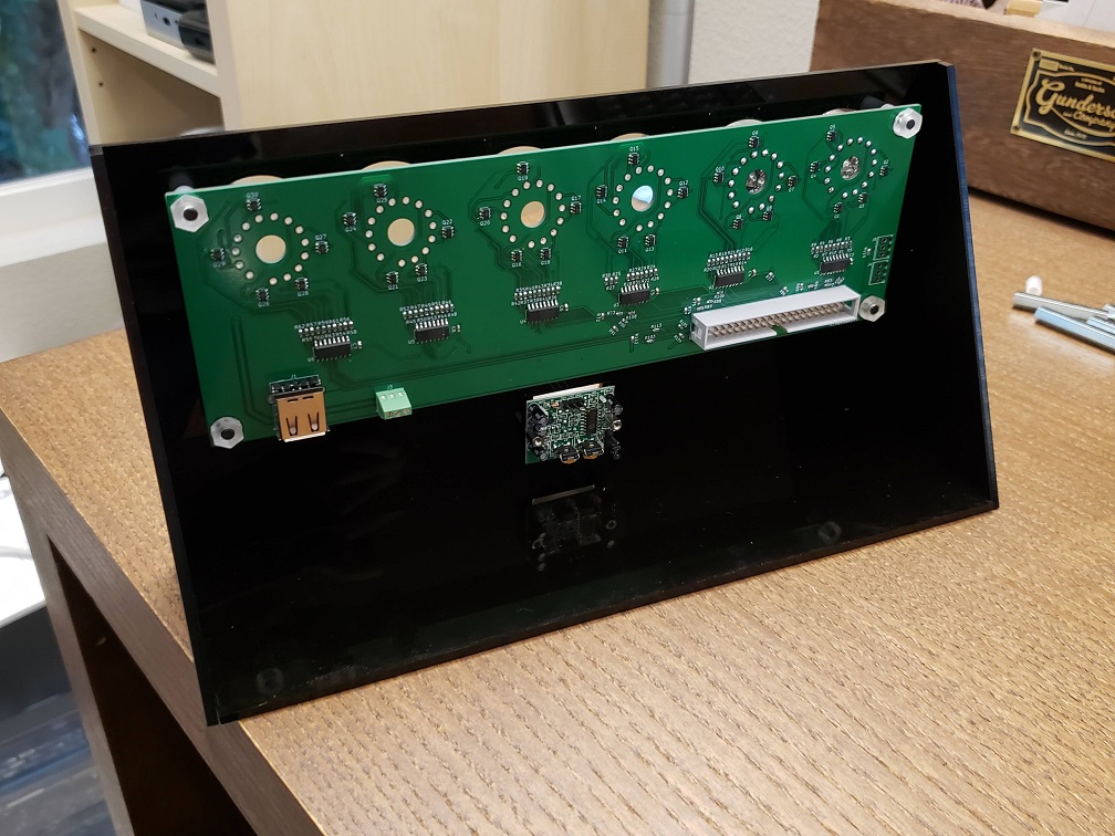
I did a quick fit test with the board and some standoffs and it looks pretty good. I’m so happy that my cut-outs for the tubes and the PIR sensor worked out well!
Front view
Back view
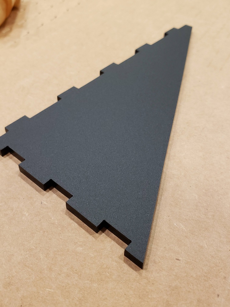
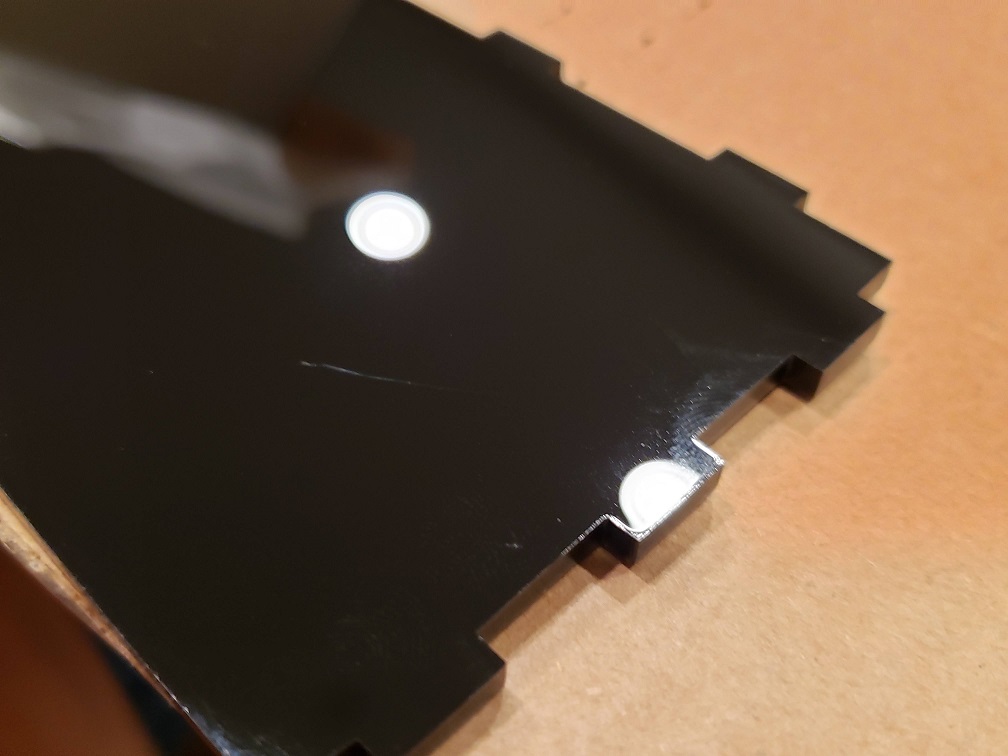
I’m very impressed with the material and with the laser cutting service. Everything fit well (if I were to remake this, I would probably shave a quarter mm from the joints as they were a little tricky to put together, but that’s on me) and I’m very happy with how it looks. Here’s some more detail on the material, which has a matte (external) and glossy (internal) side. I chose to put the matte side on the exterior because I don’t want my fingerprints all over the face of the clock, but there’s one face (the triangular face on the left) that’s inverted due to the orientation it was in when it was cut – something to thing about for next time.
Matte side
Glossy side
I also wrote a quick script to display the seconds portion of the current time on the two tubes I’ve got soldered down, and that”s worked well except for some digits missing due to some questionable solder joints.
Displaying the current seconds rather than the hours
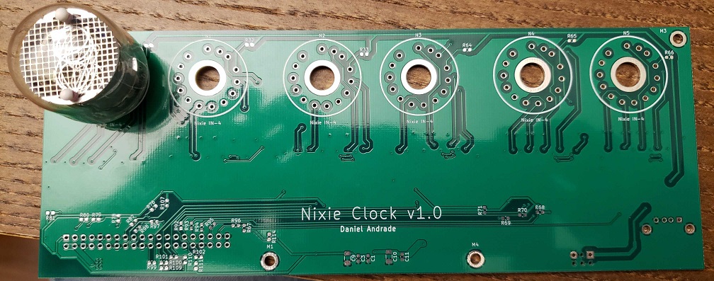
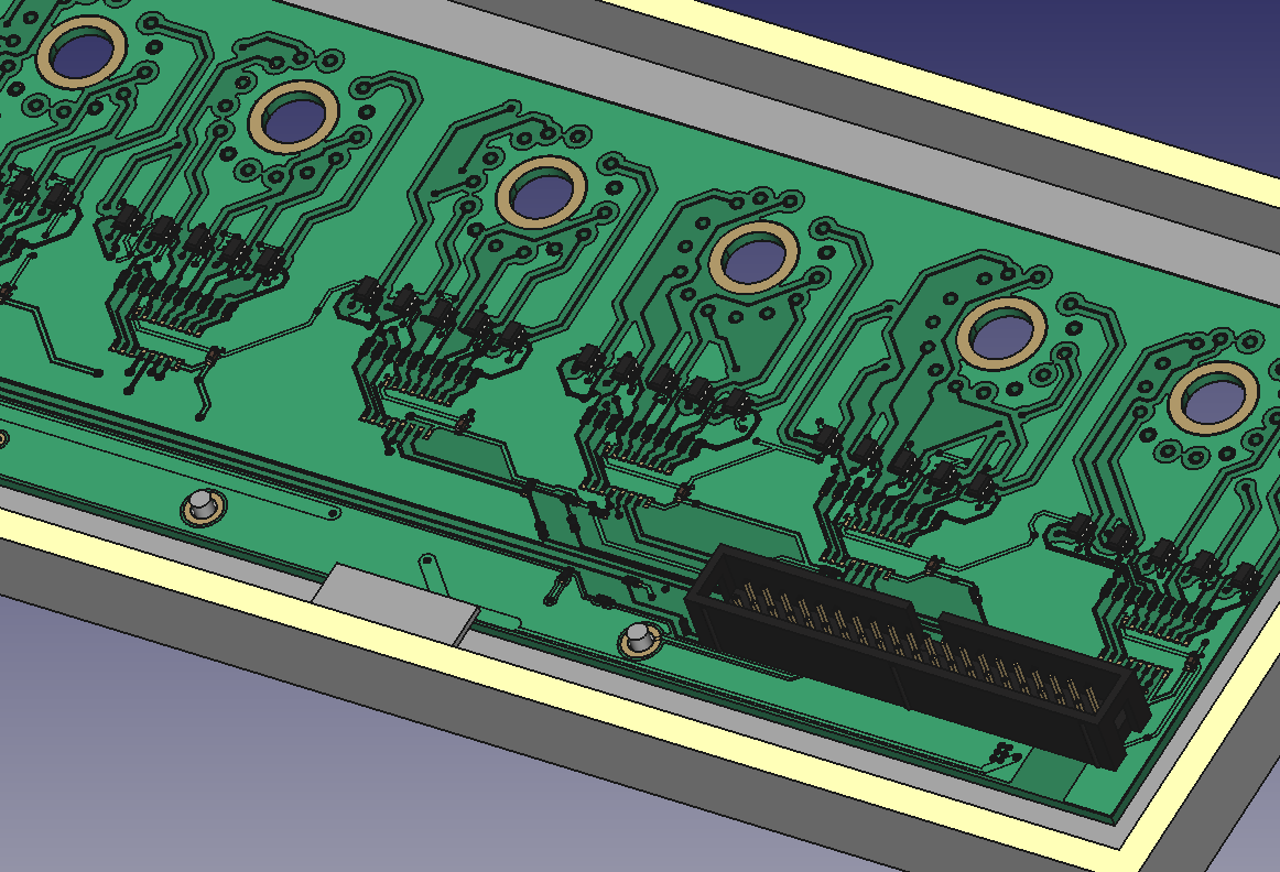
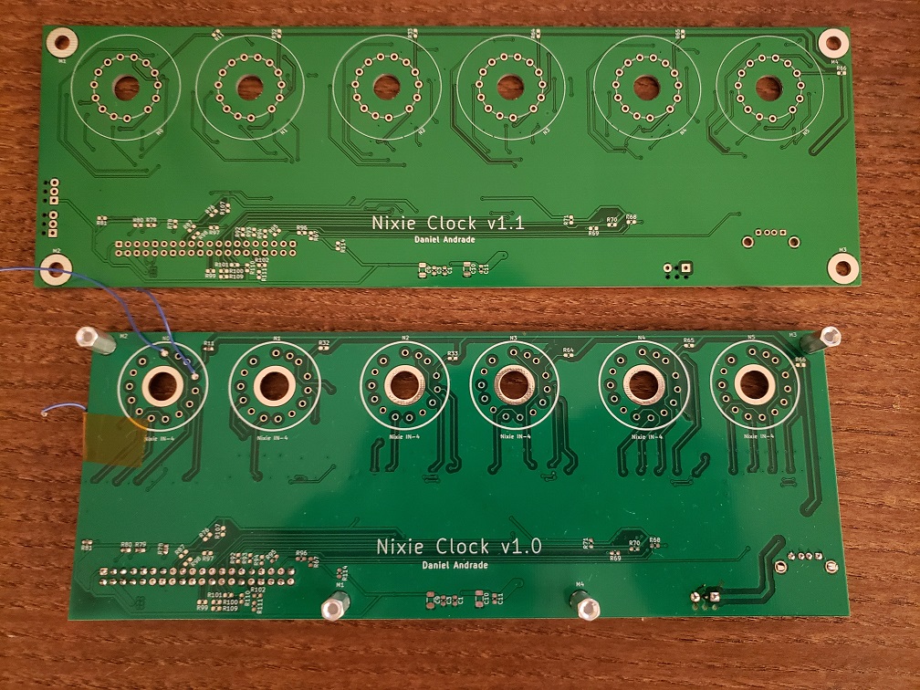
The new boards arrived early this week! Here’s a side by side comparison of the old board and the new one (notice the difference in the of the white silkscreen around the tubes – the new silkscreen reflects the actual size of the tube, whereas before I think I just plotted down a circle of arbitrary radius).
Board comparison. I’m not super jazzed about the new green soldermask color, but otherwise the new board is all right.
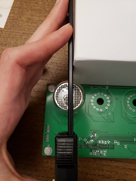
I finally bit the bullet yesterday and installed one of the tubes on the new board (after installing the decoder and series resistors and testing that out). It was a bit of a process because it turns out that the alignment of the tube itself to the pins is not completely controlled. So when I put all six of the tubes down on the board (with no solder), they were all at slightly different angles!
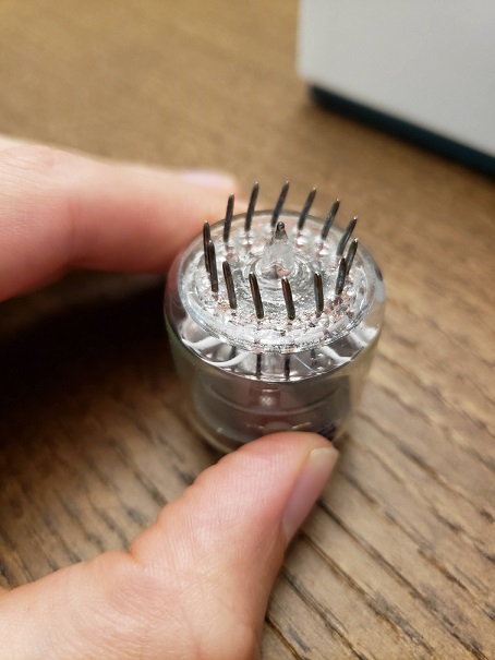
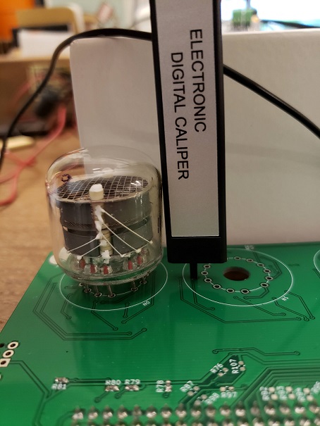
I may have to come up with a way to combat this if I want to make clocks for everyone in my family, but for now, I settled with bending the pins and aligning it manually. My girlfriend gave me the idea to align the two white dots using a box and my calipers as right angles, as seen below.
Aligning the Nixie tube using the two dots and two straight-edges
The pins turned out pretty wacky, right?
Making sure the height of the tube is even all the way around
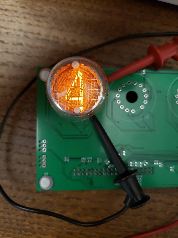
After this I tested each digit manually (by driving each pin with the supply and a series 15kΩ resistor), soldered it down, hooked it all up, and wrote a little program to count up (and then go back to zero). I made a little animation to show you!
Testing each digit before fully committing and soldering the tube down
It works!!
Now there’s no excuse. It’s time to get everything else soldered down while I wait for the enclosure to arrive!
It’s a new post in the series and this time there isn’t a new PCB! So there is hope after all…
I haven’t had much of a change to work on the electronics part of the project since the new board hasn’t arrived yet, so I’ve been mainly focusing on the enclosure design aspect. A friend of mine suggested looking more into manufacturing techniques before continuing, so I took his advice and decided I’d give laser cutting a go for my first prototype. I really like how the finished products look with this technique and it seemed cost effective for a larger design like this one.
Since a laser cut enclosure is just a set of 2D shapes of fixed thickness, I could no longer have the small features I’d designed to hold the various boards in place. In order to deal with this, I added screw holes on the front face to hold up the main board and PIR sensor. I’m planning to have the screw heads on the front face, with the screws going through a small spacer, the boards, and then a nut on the other side. I have no plans for securing the RPi and supply boards to the bottom of the enclosure for now, but I might make a ledge or something like that on a future revision. Note the hole on the right side for a button!
I like the look of this “open air” enclosure for a prototype, so I might keep that going forward. My main concern for now is that the whole thing is going to want to tilt forwards as it’ll be top heavy because of the tubes. I may have to increase the size of the base or make it heavier going forward. For now I can always weight it down with something.
2D view of the enclosure that I sent out to the manufacturer earlier today
Another post, another PCB. Hopefully that’s not par for the course…
I just sent the Rev 1.1 PCBs off to fab. I made the following changes:
Swapped out the 74HC42 decoders for HEF4028BT parts, to address the issue discussed in the previous post. This involved a fair amount of re-routing as the pinout was quite different.
Changed the footprint for the nixie tubes and rotated them 180 degrees so that the board can be mounted right-side up on the enclosure
Added screw terminal headers for connecting the PIR sensor and the switch to the board (they will both be mounted onto the enclosure itself, so they will need to wire into the board)
Moved the BJTs closer to the nixie tubes to shorten the length of the 40-70V collector traces
Grew the board’s width by 30mm and re-arranged the nixie tubes so that they’d be spaced a little further apart
Changed the M3 mounting holes into M4 ones. I had the space and the M3 posts on my enclosure were looking a little fragile.
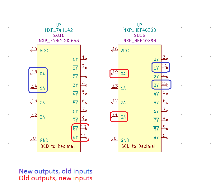
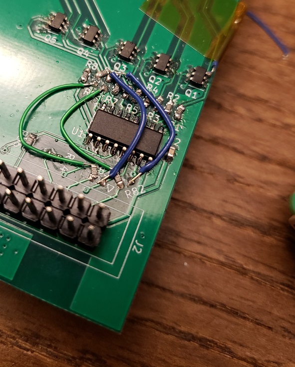
In parallel, I reworked one tube’s worth of the current board to work with the HEF4028BT to make sure that the interface between than and the RPi was OK (the part’s power pin is specified down to 3V, but the input high level is only spec’d when it’s powered off 5V, and it’s 3.5V) and that it wouldn’t have a problem driving the BJTs. It seems to have worked well. In order to make it work, I had to at least re-route two of the previous outputs to the Raspberry Pi and vice-versa, see below. This would ensure that inputs would still be connected to inputs and outputs would be connected to outputs. However, doing only this leaves the logic table very scrambled! I wrote down the options and “decoded” (pun fully intended) the logic.
Here’s the min required input/output swap on the board. Thank goodness for series resistors!
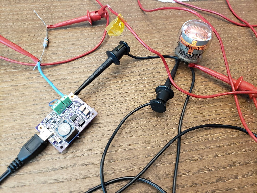
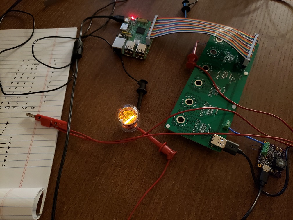
I didn’t want to solder a nixie tube onto the board to test it since I’d need to de-solder it later (to put it on the new board) and that wouldn’t have been the most fun without clipping the leads. So I soldered a single digit (the “1”) up to a wire which I then hooked up to the tube with clips. You can see a picture of the full system in action below.
Full system wired and working together for the first time!
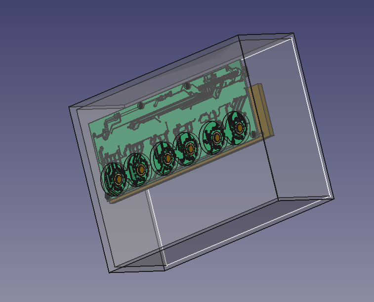
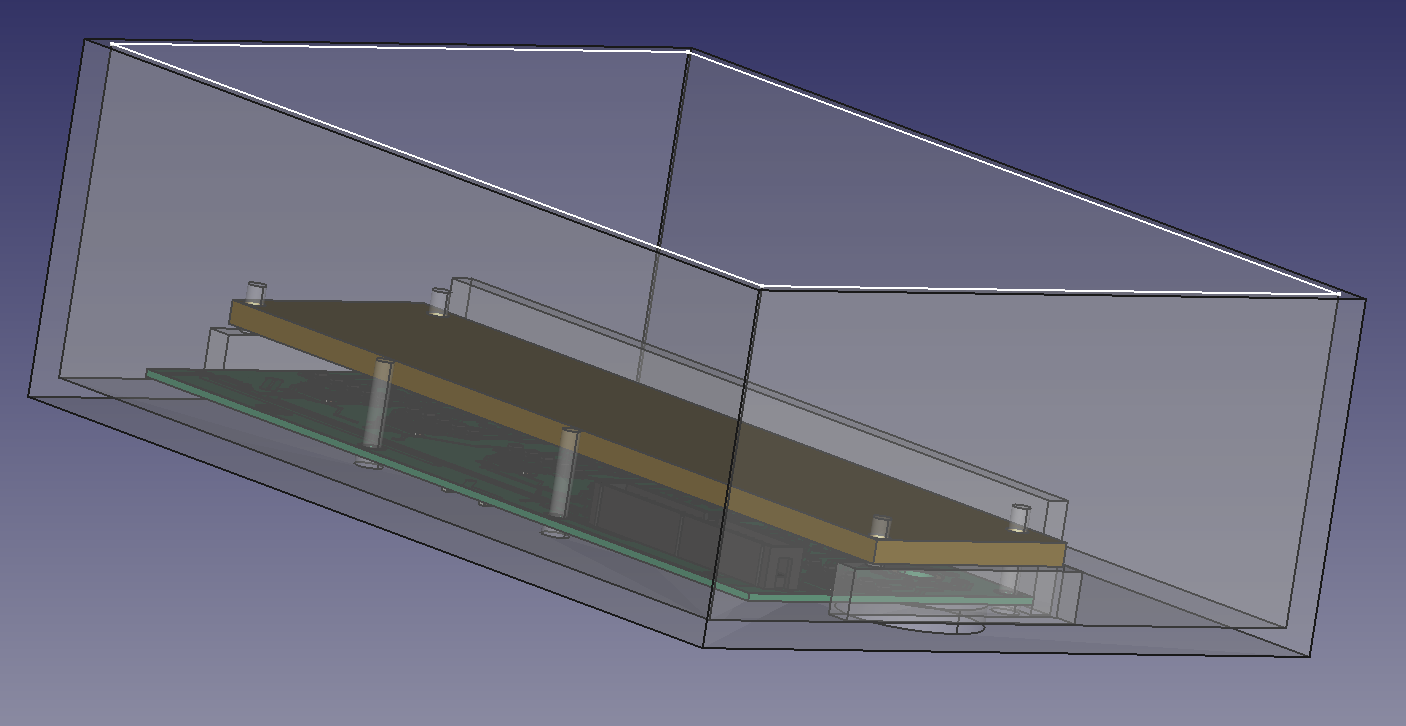
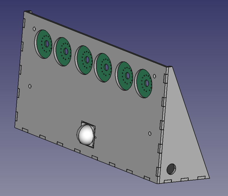
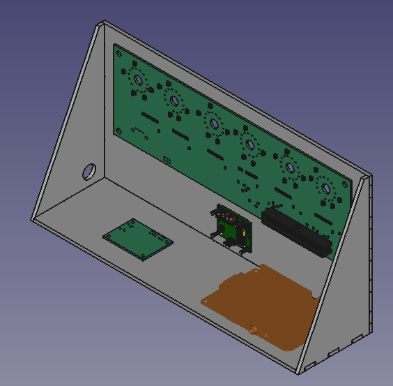
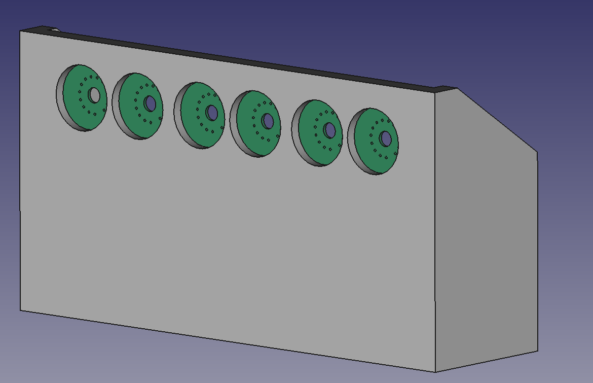
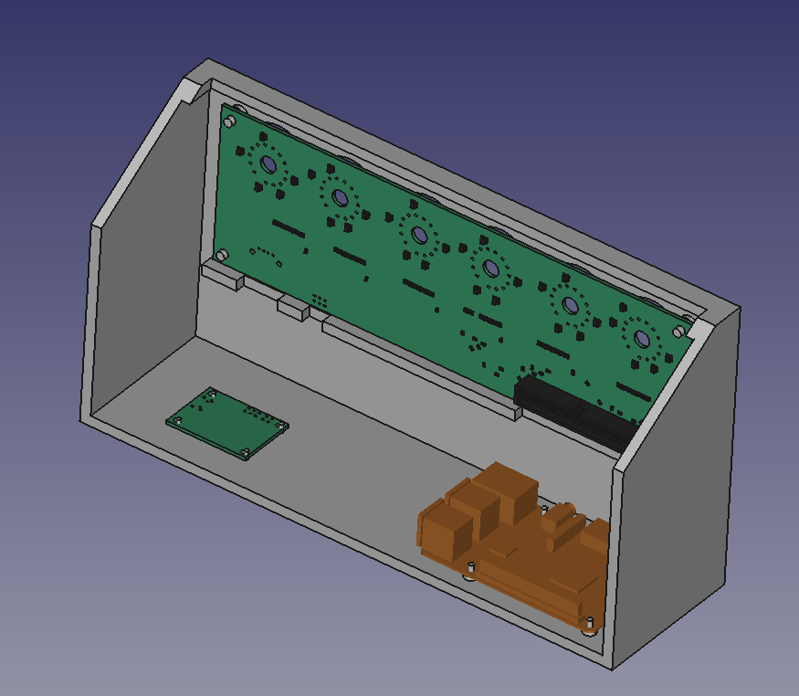
I’ve also scrapped the previous version of the enclosure (which had the board mounted upside down) and started over. Here’s some shots of the new enclosure design with the Raspberry Pi, power supply, and main board shown.
Front view
The brown board is the RPi 3 model, the small board is the 5V to 170V supply
I have a Raspberry Pi 3 that was sitting around most of the time, so I recently started working on a Raspberry Pi powered nixie tube clock. It’s a pretty basic project and I’m not quite done yet, but I’ve already run into several snags, some which are only natural since I didn’t have any experience with CAD (and I didn’t own a pair of calipers…) and others which I’m a little more embarrassed to admit. Let’s get into it!
Concept
I want to make a simple six digit (HH:MM:SS, no colons) clock, with one tube per digit. The Raspberry Pi can get the time from the internet (through WiFi so there’s no need to support an Ethernet cable going into the enclosure), and maybe display some home statistics from bluetooth sensors that I can scatter around the house (temperature and humidity come to mind). These statistics should be stored on the RPi’s SD card so that I can later retrieve them through SFTP for further processing (e.g. graphing). I’d like to have a single button which I can press to cycle through time, indoor temperature, outdoor temperature, and humidity. Lastly, I’d like it to have a PIR motion sensor for turning on the clock only when someone is present (to preserve the tubes, since their lifetime appears to be in thousands of hours). Since I’ve never used CAD for any kind of mechanical design, I want to challenge myself to design and 3D print (or otherwise manufacture) an enclosure. It doesn’t have to be anything fancy, it can just be a box that holds the boards, has cutouts for the button and the tubes, and doesn’t rattle or fall apart when it’s all put together. It is by embracing low standards that we arrive at success, but, at the end of the day, I may very well be looking at this thing every day, so I don’t want it to be too ugly.
An image for inspiration. Mine won’t look this good, but hopefully won’t make me regret doing this every day, either.
Circuit
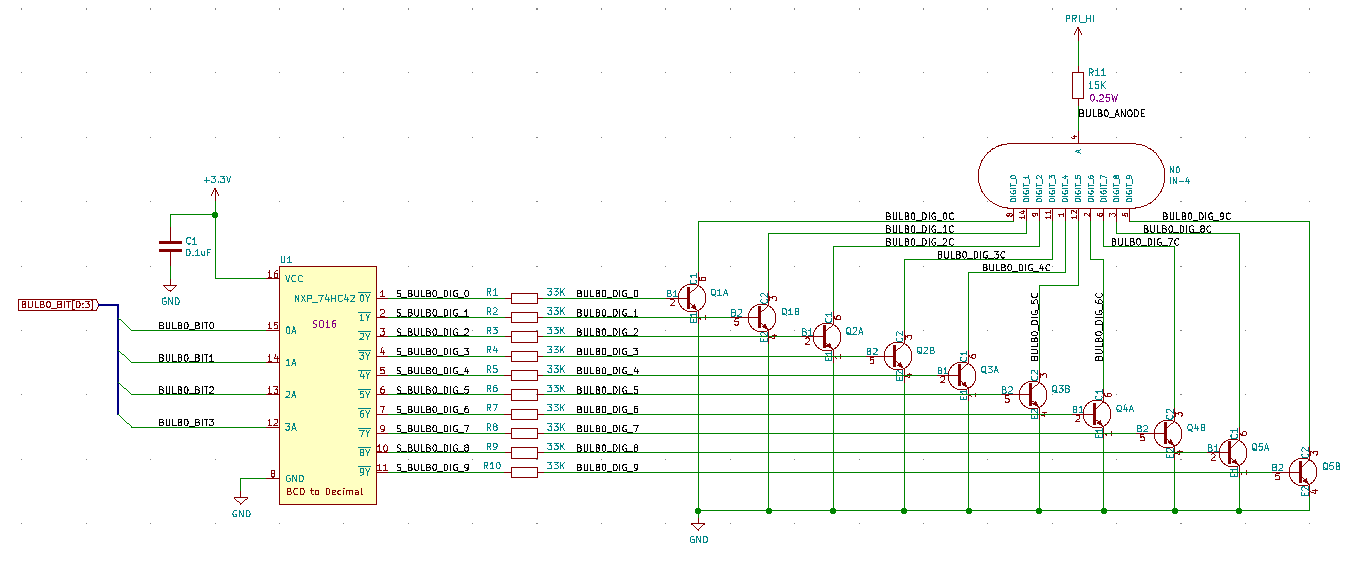
For the uninitiated, nixie tubes are gas discharge tubes (GDTs) which work in a similar fashion to a neon sign: a high voltage is used to ionize a noble gas inside of the tube, making it glow a bright color. There are metal pieces (cathodes) bent to look like digits that are at a high voltage, causing the glowing ionized gas to crowd around the digit and make light in the shape of that digit. From a circuit point of view, nixie tubes work more or less like LEDs – the anode is connected to a high voltage (in this case quite high – 160V or more) and the cathode corresponding to the digit you want displayed is grounded, with a series resistor somewhere in there to limit the current to around 3mA. Although the nixie tube requires 160V to light, once it is on it will drop less voltage, typically around 130V.
From that description, here’s the basic building blocks that we need:
A boost converter from 5V (from the Pi) to 170V. I found an open hardware design (and more nixie tube resources) on SURFNCIRCUITS, so I ordered some of his boards and assembled one myself.
60 (!) GPIOs to control the digits (10 digits, 0-9, for six tubes). I decided to use a 1 of 10 BCD (binary coded decimal) decoder to convert 4 control lines into ten lines. That gets me to 24 GPIOs, which I have on my RPi. This could be reduced further by multiplexing the display quickly so as to only drive 1 tube at a time, but I didn’t pursue that.
A way to drive the cathodes to ground. A popular solution seems to use old Russian chips that were meant to do exactly this (drive nixie tube digits, e.g. the 74141), but I settled on using 30 dual NPN MMDTA42 high voltage BJTs since the Russian chips are tricky to find.
Here’s a snapshot of what we have from the above from a schematics point of view (for each nixie tube):
Schematic snip for single nixie tube
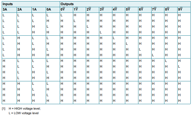
Here’s where the first mistake comes in. You’ll notice that the 74HC42’s output pins are inverted, so the logic table is as follows:
From Nexperia’s 74HC42 datasheet
Notably, no matter what input you put in, all the chip will do is ensure that only one output is low! This is the opposite of what we’d like for driving NPN transistors! I somehow (didn’t think very hard) convinced myself I could just fix this in software by inverting bits, but this is clearly not the case…Consequently, I have swapped the chip for Nexperia’s HEF4028BT, which has only one bit high all the time (noninverting outputs). Unfortunately, the pinout is a little different, so I’ll have to re-spin my boards (or suffer a lot of rework), but that’s how it goes!
There’s a couple of other missteps that have more than convinced me to re-spin the board. Firstly, the nixie tubes are upside-down. You can sort of tell this is the case if you stare at the picture of the board with the tube on it. Additionally, the location of the fourth pin on the footprint is a little off; you can force the tube in there, but it really bends that lead. I considered mounting the board upside-down and clipping that lead (and connecting through a blob of solder), but the 74HC42 blunder really sealed the deal on getting a new board.
In my defense, the only resource I could find on the footprint of this tube was this diagram, which, well…leaves one wanting. And I double checked my math on that fourth pin and I still think I did it right, so, who knows! For the new board I’ll use Mark Smith’s footprint from SURFNCIRCUITS since I know he’s actually built IN-4 nixie tube clocks.
I found it very odd that the angle was described in terms of minutes…And that’s a lot of trigonometry that can go wrong!
The good thing about redesigning the board is that I’ve had more time to think about what I’d like from this project since the first spin. I’ve added the button and PIR sensor requirements, and now I’m also thinking of arranging the digits in a more creative way, perhaps slanted in 45 degree angles. Because I’m taking my time with this project, I don’t really mind the delay.
That’s all I have for today, so here’s a couple of galleries of the debug and enclosure design processes!
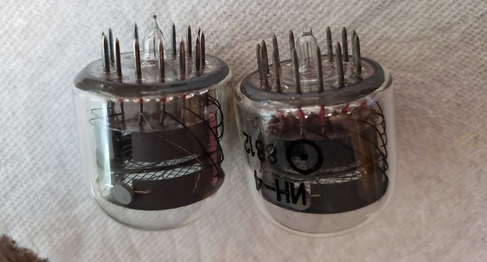
First boards that arrived in July
Removing 40+ years of oxidation on the nixie tube leads (compare left to right)
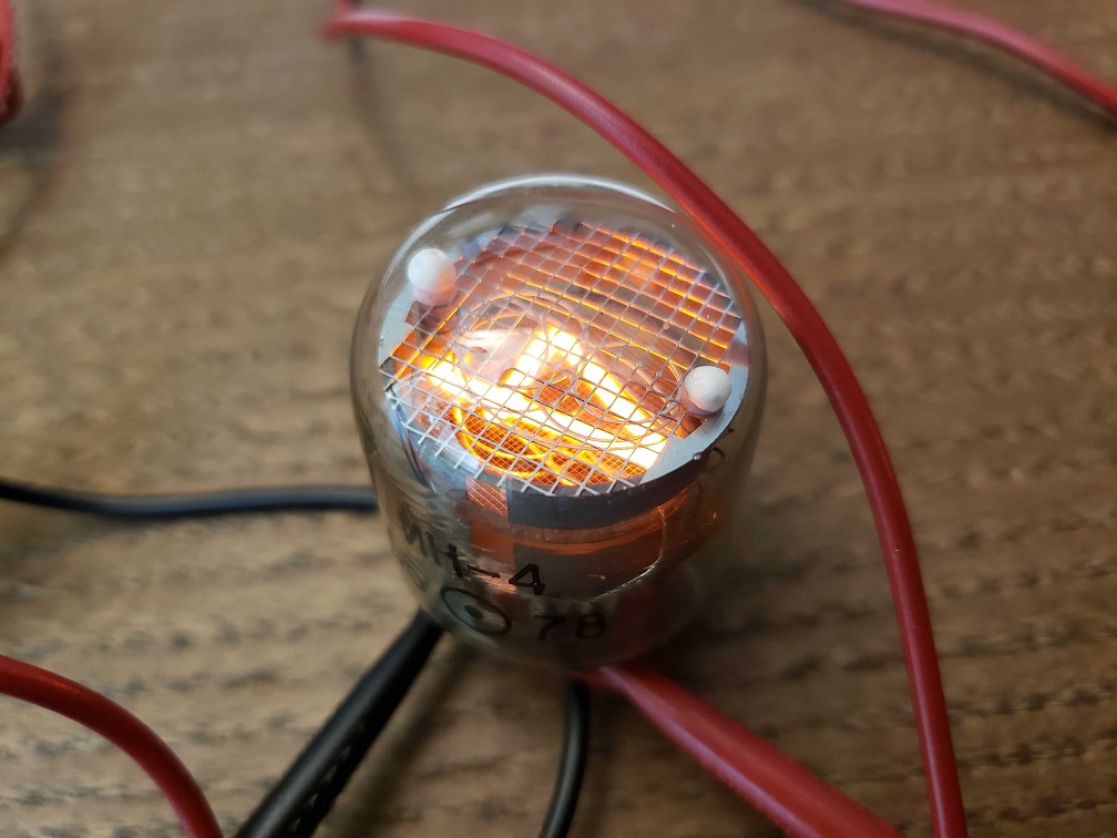
Testing out the nixie tubes when they first arrived
First time seeing a digit on a nixie tube!
Front view
Side view
Check out the detail that KiCAD brings into FreeCAD!
")
")


")
")
")

")
")