
The very nice thing about making a project that’s just for us to use (as opposed to a product we’d like to sell) is that we can take bits of people’s hardware designs and/or code and use it with abandon – or at least without having to worry about a potential copyright violation. In this particular post we’re going to go over how to run the code examples ST provides for interfacing with their eval board hardware and look at the code for their LTDC paint example, which may become the foundation upon which we do the drawing of elements on our screen for this oscilloscope.
As I’ve mentioned before, ST maintains a collection of examples and “applications” called STM32CubeF4 that showcases the capabilities of the microcontroller when it is connected to the different components on the evaluation board. Here you will find anything from small snippets of code going over how to set up a timer to full-blown applications like LTDC Paint which emulates a simple “MS Paint”-like program on the display (LTDC stands for “LCD TFT Display Controller”, where “LCD” and “TFT” are their own acronyms).
Some of the Cube examples are simple or focused enough that the only thing we’d like to do with them is look at the code to see how something works (like setting up a timer or playing around with interrupts). The applications, however, are more or less full-fledged ideas that we’d like to run on the board and interact with. ST provides the source-code for everything without the binaries, so first we have to figure out how to set up and build the project on SW4STM32. Let’s delve on how to do this first.
Building and Running STM32CubeF4 Projects
I’m a little embarrassed to admit that it took me about an hour and a half to figure out how to do this – I know that because I had just configured my bread machine to knead and rise a pizza dough for me and that’s how long that process takes. In my defense, the STM32CubeF4 folders are set up in a way that makes them look like you’re just supposed to open up a project inside of them and have it all magically work…
Anyway, let’s go ahead and set up the LTDC Paint example step-by-step so that we can run it. Below you’ll see a screenshot of the folder corresponding to this example inside the STM32CubeF4 directory (Projects/STM32F429I-Discovery/Applications/Display/LTDC_Paint):
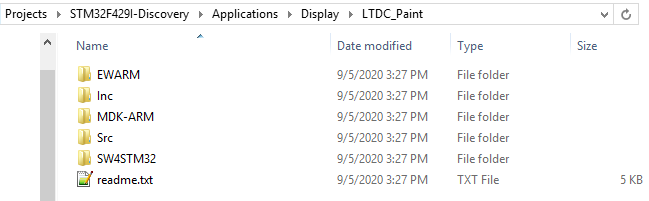
If you’re like me, you’ll see the Inc and Src folders and think all you have to do is start a new SW4STM32 project in here (or in a copy of this directory) and then link it all together inside of Eclipse somehow. That is absolutely not the way to do it. The problem with this approach is that this folder is not all there is to this project – it uses code from the Utilities folder all the way up at the root of the STM32CubeF4 directory, and the correct linking for all these files is in the “SW4STM32” folder of the LTDC_Paint application.
Here’s the process for getting this or any other project loaded into ST4STM32 correctly. Open up the IDE in your preferred workspace (it does not have to be where you have the STM32CubeF4 files stored) and select File->Import. A submenu will open from which you should select “Existing Projects into Workspace” under “General.” In the next window, select the SW4STM32 folder (not the LTDC_Paint directory) as the root directory (for example, Projects/STM32F429I-Discovery\Applications\Display\LTDC_Paint\SW4STM32). Once you do that, “STM32F429I-Discovery” should show up as an option (side-note: this means you can’t already have a project in your workspace called “STM32F429I-Discovery,” which is kind of annoying since they’re all called that…if you do, just remove it and start over). It may be a good idea to select “Copy projects into workspace” to create a copy to leave their example untarnished, but you can also download the example again if something happens.
[It’s probably good to mention here – do not rename the projects to something other than STM32F429I-Discovery – it’ll break how the files are linked and changing it back will not fix it! If you run into this, just download the files again from ST’s site, or figure out a way to fix it and let me know!]
At this point, you can hit “Finish” and you should have a new project in your workspace (or linked to it from elsewhere) called STM32F429I-Discovery” which you can build and try out. In this case, “LTDC Paint” is a MS-paint-like program that runs on the LTDC touchscreen (by the way: the code is under the “Example” folder):
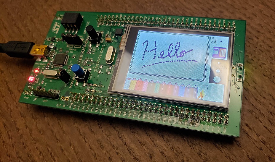
ST’s LTDC_Paint application running on my evaluation board
That’s great, but what does this do for us?
Well, we can use ST’s code as a template for all the drawing to screen we need to do for our oscilloscope, from text that shows our trigger level and cursor settings to the dots that make up the waveform we want to show the user. The functions in LTDC_Paint help abstract certain aspects of how the DRAM and display work, so that all we have to do is call functions such as:
| Function | Description |
| BSP_LCD_DisplayOn() | Initializes the display |
| BSP_LCD_Clear(COLOR) | Clears the display and draws a solid background of the color provided |
| BSP_LCD_FillRect(x, y, width, height) | Draws a filled rectangle of specified width and height at position (x, y) |
| BSP_LCD_DisplayStringAt(x, y, text, mode) | Draws some text at (x, y) |
There are also some very helpful definitions of fonts and color configurations which we can copy and use as we wish!
We can similarly take other bits and pieces of code from ST’s applications and examples to get the functionality we want for timers, interrupts, and other processor configuration code we’ll need. For the next update, I’ll attempt to modify the LTDC_Display code to display some axes and other simple display elements we’ll need on the oscilloscope screen. Stay tuned for this and, soon after it, some initial work on building the triggering circuitry from logic gates; you know I can’t have too many consecutive posts about software – I am a hardware engineer, after all!