Scope Part 1 – What’s Important in an Oscilloscope?

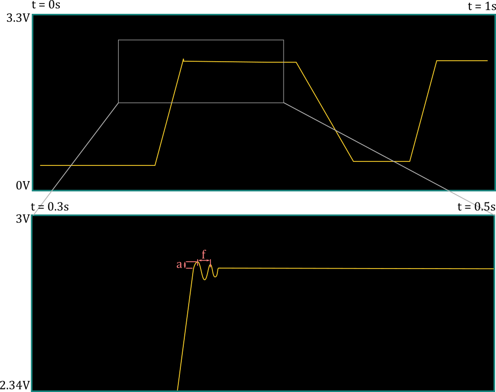
Example of zooming in to a signal on an oscillocope

What is an Oscilloscope?

An oscilloscope (or just “scope” if you’re far enough removed from microscopes for it to not be confusing) is a tool that measures and reports voltage over time (a “signal”). Modern oscilloscopes are digital and will show the signal (or various signals at the same time) on a LCD screen. There’s a host of buttons that control which part of the signal is shown and when (and/or how often) the signaled should be “sampled.” It’s a very useful tool that lets you verify that the signals on your board are actually doing what they’re supposed to do, without degrading too much in the process.

Let’s get into it below.

So – what makes a scope good?

It should go without saying an oscilloscope should be accurate and should introduce as little noise as possible. You want to make sure that what you’re seeing on the screen is what is actually going on where you’re probing. This is a simple concept to understand, but it’s easier said than done.

An oscilloscope should also be as generic as possible – ideally, you want an oscilloscope that is a “one size fits all solution”; you don’t want to reach for different oscilloscopes when working on different parts of your project. What this means practically is that you want to be able to “zoom in and out” of the signal in both the vertical and horizontal axis (as well as shift it up and down and left and right). This will make your oscilloscope be able to display the widest variety of signals – small or large (y-axis), fast or slow (x-axis). It will also allow the oscilloscope to look at a single signal in various ways (zoomed-out on the x-axis for long-term, steady state behavior or zoomed-in on the x-axis for short-term “transient” behavior, such as spikes or noise, for example).

The vertical axis represent voltage, so to “zoom in” you need to amplify (increase the amplitude of) the signal and to “zoom out” you need to attenuate (decrease the amplitude of) the signal. This is done in what we call the “analog front-end” of the signal. The horizontal axis represents time, so to “zoom in” we’ll need to take samples more frequently and to “zoom out” we’ll add more time between the samples. Here’s a quick example:

What is actually happening when we zoom in like in the above example? We can say that we adjust the “screen” so that it goes from showing what it was previously to being filled by only what’s in the grey box. That is, the screen is now limited to showing a “subset” of what it showed before – instead of voltage going from 0V (bottom of the screen) to 3.3V (top of the screen). now it only goes from 2.34V to 3V. Likewise, the time scale has been reduced – now it only goes from 0.3s on the far left of the screen to 0.5s on the far right of the screen. This sounds a lot like a “digital zoom” on a camera, but if we take a closer look at the second image, we see that we didn’t simply reduce the amount of information – we now have more information about the little “spike” we saw in the zoomed-out version. What before looked like a simple “spike” now looks like oscillatory behavior with an overshoot of a and a frequency of f.

To understand what’s going on, we have to know what’s going on in the guts of the scope to show you this signal on the display. Here’s a simplified block diagram of the hardware that obtains the signal to be displayed (we’ll expand on this later):

The microcontroller (MCU) is the brains of the operation – it runs the code that we write and tells the display what pixel goes where (and in what color). A microcontroller by itself, however, does not understand an analog signal; it works purely in the digital domain – ones and zeroes, or 3.3V (or other IO voltage) and GND. The MCU also doesn’t have a sense of “analog time” – it’s fed a clock from a crystal oscillator or other source, and runs an instruction (think of a line of code) every tick (this is again an oversimplification, but it’s a good enough description for our purposes).

The MCU needs a series of digital signals that somehow map to the original analog signal. This is the job of the ADC (Analog to Digital Converter), which takes in an analog signal at the input as well as a digital clock and spits out the “digital equivalent” of that signal at the output whenever the clock goes from low to high (or sometimes high to low). The voltage range at the input of the ADC, however, is limited within a certain range, typically (but not always) between ground and the ADC’s supply (3.3V or 5V, for example).

This is why we have an analog front end – it needs to process the analog signal so that it fits within the dynamic range of the ADC (the min and max voltages at the input that it can understand). It’ll need to make the signal bigger or smaller (scale the amplitude of the signal linearly) as well as shift it up and down so that the user’s desired range/window is within the ADC’s dynamic range. This amplitude factor (gain) and offset will need to come from the MCU so that the user can configure how the signal is seen on the screen.

We need something else between the MCU and the ADC. The ADC will be sampling the signals constantly; in order to support a wider range of “zooming” on the signal, we will sometimes need to sample the signal very often, if the user wants to zoom way in on the signal. For instance, if the user wants to the screen’s width to be 1us, the screen is 300 pixels wide, and we want each pixel to represent a sample, we’ll need to take a sample every 1us / (300 px/sample) = 3.33ns, which is a sampling frequency of 1/3.33ns or 300MHz (that’s very fast)! Realistically, we wouldn’t do a sample per pixel – we can start with a sample every ten pixels and connect them with a line – but you get the point. We’ll see that the ADC cost starts to increase astronomically with the maximum sampling frequency, so that will be the limiting factor here – probably somewhere around 50-60 MHz; I’ll show you the options and we’ll do the analysis together. In any case, the MCU cannot handle 50 million samples a second. Let’s say a typical embedded processor runs at a clock frequency of 200MHz – that’s 4 cycles per sample if we’re sampling at 50MHz – there’s no way it’ll be able to do the triggering, processing, displaying instructions, and anything else it needs to do in those four cycles of “free time” before the next sample comes in!

What we need to think about here is that, in practice, most samples a scope takes are thrown away and never displayed. That makes sense – there’s no way a human brain would be able to processes 50 million (distinct) samples a second (although you would get some benefit from displaying 1000 samples that were an average of 50 million – but let’s put that aside for now). The scope setting that determines which samples are thrown away and which are shown on the screen is called the trigger. Triggering circuitry can be arbitrarily complex, but at its simplest the user configures what threshold voltage they’d like to see, and whether they’d like to see the signal cross that voltage from below (rising edge), above (falling edge), or both. The scope then displays samples around that triggering voltage – typically some samples that happened before it and some that happened after (the exact delay between the trigger and the samples shown on the screen can also be configured by the user). The trigger can also be set to “auto” – which means the scope will “continuously” show samples – but realistically, this doesn’t mean you see all the samples. In fact, what most scopes are doing is waiting for a trigger event to happen, and if they don’t see one, then they will trigger themselves after a preset “timeout”, which makes it look like the scope is running continuously.

What this means in practice is that the MCU doesn’t need to look at every sample from the ADC – what we should try to have instead is some hardware that looks at every sample and figures out if a trigger event has happened. This same hardware can be responsible for saving the samples to memory (remember – both before and after the trigger, so we need to be continuously storing the samples, not just after we see a trigger) and managing the memory so we don’t overflow it with samples that we’re never going to need. Once the trigger has happened, our circuitry can let the MCU know that it needs to get the samples and can tell it where exactly in the memory to look for the samples. The MCU can then take its time, read the samples out of memory, and display them.

Here’s what we need, then, to make an oscilloscope that is as generic as possible – each of these will warrant several posts of their own:

  • An analog front end with a variety of MCU-controllable settings to both scale the signal as well as offset it
  • An ADC capable of sampling the signal as fast as possible without breaking the bank
  • A flexible and MCU-controllable triggering and logic circuit to process and store the “interesting” samples coming out of the ADC.
  • A good amount of memory for the samples, so that we can support a delayed version of the signal (make the signal move left or right on the scope screen)
  • A decently fast MCU and a good display to make sense of the samples

Don’t worry if there are parts of the above concepts that seem too complicated to grasp now – we’ll delve into each of these elements in more detail individually (and if you’re angry that I got a lot of stuff wrong or oversimplified, I hear you – I’ll be learning more throughout this process too). What I’m hoping you’ll get from this, however, is that hardware design is often fitting blocks together to get what you want. You start with what you know (“I need an MCU”), figure out what it can’t do (analog signals), find a component that can (an ADC), and iterate from there (“the ADC’s input dynamic range is limited”). This is one of my favorite aspects of hardware design, and I hope it intrigues you, too!

Nixie Clock Project (Part 7 – It Works!)

Nixie Clock Project (Part 7 – It Works!)

We did it, folks! It’s at least functional, which is more than I can say for a lot of my own personal projects that I’ve started! I’ll even dare to say that I think this even looks better than the inspirational picture I posted on my first post!

The clock shows the time, the internal temperature, the external temperature (based on querying OpenWeatherMap API with the right city code), and the AQI (air quality index using the AirNow API – a good idea for us in the west coast of the US who happen to be experiencing a lot of smoke in the air!). Right now I’ve got it alternating between the time, the internal and external temperatures (in one screen), and the AQI. The temperature units can be set to Celsius or Fahrenheit. Right now I cycle between these three “screens” every 20 seconds.

The PIR sensor is working well, too! I tuned the time it would have to go without seeing motion to fall asleep to a minute; this seems to work well because it’s enough time to cycle through all three screens and because I put the clock in a rather central location where it’s easy to wake it up by waving at it. The sensor has a 7m range in a 120 degree cone, which turns out to be just about perfect. I was having issues making it work initially and then I realized that I was giving it a 3.3V supply when it wanted to be connected to 5V – oops! In my defense, it specs 3-5V on the Adafruit website, but then there’s a little bit of text saying that if you want lower voltages to work you have to bypass the regulator on the PIR sensor board which I completely missed. It was easier to connect it directly to 5V instead, so I went ahead and changed the wiring to make that work. I’ll clean up the code a little bit more, edit my code post from last week, and post it there.

The project is more or less “done” now, but I’ll do a couple more review posts where we’ll look at reducing the cost of the whole product as well as making it easier to put together. Specifically, I’d like to:

  1. Improve the nixie footprints by rotating them clockwise slightly and make all of the holes significantly larger; this should allow the person soldering the tubes to rotate them in position and then solder them.
  2. Move the power supply onto the main board
  3. Remove the 40pin ribbon cable and allow a RPi Zero W to be directly connected instead (via a 90 degree header). Margaret has one that I can try to make sure it works OK (I can’t think of why it wouldn’t)
  4. Clean up and fix a few things on the PCB
  5. Try out multiplexing the tubes; if this looks good, I’ll do so on the final clock to reduce the number of necessary IOs. That will allow me to add a SPI/I2C temperature sensor to put on the board for a better sense of the room temperature.

I’ll also keep you updated on any new feature changes or other things I try, of course. One thing I’m thinking of doing is buying a Bluetooth temperature and humidity sensor like this one (you can bet that’s not an affiliate link!) and connecting it to the clock.

Nixie Clock Project (Part 6 – Code)

Nixie Clock Project (Part 6 – Code)

I haven’t posted in a little while – I’ve been putting off soldering down the nixie tubes onto the board (mostly because it’s a little annoying to bend the pins so that the tubes are vertical), so I’ve been working on writing the code for the project. I’m periodically interspersing the tube soldering, so I’ve only got two left! Anyway, I realize nobody wants to just see a bunch of code on a blog post, so bear with me as I try to make the information a little more digestible while preserving the important bits of this part of the project.

Language

The Raspberry Pi will run basically anything you’d like on it as it’s just a Linux box. I decided to code this up in Python for simplicity and because I’ve done plenty of GPIO toggling in it before. However, you may notice that the design is very procedural, as if it were written in C – I guess my mind went to that immediately when I thought of doing an embedded systems project; now that I think about it, it may be more prudent to design the code in a more object-oriented kind of way – by, for instance, creating instances of objects for each nixie tube that hold member variables for their IO lists and states as well as member functions for writing a digit and so forth. I may overhaul the code, but this works for now.

Initialization

I designed the code such that there would be no global variables, although I do have “constants” (Python can’t enforce that they stay constant) that are global. Here’s the constants, divided by category:

NameValueDescription
SLEEP_TIME30Number of ms to sleep between every cycle of the main loop
CYCLES_PER_SECOND1000 / SLEEP_TIMENumber of code loops (cycles) per second
SECONDS_PER_MINUTE60The number of seconds there are in a minute (now that’s a constant!)
EXT_TEMP_UPDATE_SECONDS15 * SECONDS_PER_MINUTEHow often (in s) to update the external temperature (the API call is a little slow)
INT_TEMP_UPDATE_SECONDSSECONDS_PER_MINUTEHow often (in s) to update the internal temperature
Constants for keep track of time
NameValueDescription
BUTTON_IO10IO pin on the Raspberry Pi header to which the button is connected
PIR_IO8IO pin on the Raspberry Pi header to which the PIR sensor is connected
BUTTON_PRESS_INIT_VALCYCLES_PER_SECOND / 15How long the button needs to be held down for to register a press – for deboucing (2 cycles)
BUTTON_HOLD_INIT_VALCYCLES_PER_SECOND * 3How long the button needs to be held down to register a hold (3 seconds)
PIR_DETECT_INIT_VAL1 * CYCLES_PER_SECOND * SECONDS_PER_MINUTEHow long the PIR detector has to go without detecting motion before putting the Nixie tube display to sleep (1 minute)
Constants for IO interfaces

In addition to the above constants, there’s also a few constants required for the API calls (the strings and API keys) in the file nixie_helpers.py, as well the constant ROOM_TEMP_OFFSET, which is the temperature offset in Fahrenheit between the CPU temperature and the room temperature. I calibrated this out with a thermometer and it’s around 34°F at my place.

The sole initialization function is initGPIOs(), which builds and returns a list of lists, where each one of the lists corresponds to the IO pins connected to the four bits driving the nixie tube decoders of that digit. So, for instance, the numbers in dig_H1 = [11, 7, 5, 3] correspond to the four IOs connected to the four binary bits on the decoder driving the tube of the first hour digit. This (and the rest of the connectivity) is illustrated below.

The function then initializes these GPIOs, configures them as outputs, and initializes the input GPIOs corresponding to the button and PIR sensor. The list of nixie tube IOs is returned to the Main() function to be used later for displaying the digits.

Variables

The variables are all initialized and kept track of locally in the Main() function. Here’s the table of these variables:

NameValue at InitializationDescription
button_press_timerBUTTON_PRESS_INIT_VALHow long the button must be held down for checkButton() to register a button press (this is done with the timer reaches zero)
button_hold_timerBUTTON_HOLD_INIT_VALHow long the button must be held down for checkButton() to register a button hold (puts the clock display to sleep or wakes it)
pir_timerPIR_DETECT_INIT_VALHow long the PIR sensor must go without detecting motion to put the clock to sleep (also done when the timer reaches zero)
current_modeMode.TIMEThis is set to an IntEnum type that tracks the current mode – TIME, INT_TEMP (CPU temp), or ALTERNATE. I’m planning on adding an EXT_TEMP to get the external temperature later.
is_asleepFalseWhether the clock is asleep (True) or not (False)
IO_listreturn value of initGPIOs()The IO list of all the Raspberry Pi IOs connected to the decoders driving the Nixie tubes
tempCurrent external temperatureThe external temperature. This variable gets updated every EXT_TEMP_UPDATE_SECONDS
aqi_catCurrent AQI categoryThe current AQI (Air Quality Index) category, from good to hazardous. This variable also updates every EXT_TEMP_UPDATE_SECONDS
aqi_numCurrent AQI numberThe current AQI number, from 0 to 500. This variable also updates every EXT_TEMP_UPDATE_SECONDS
last_weather_timeNowThe last time the external weather was updated
int_tempCurrent room temperatureThe current room temperature
last_int_temp_timeNowThe last time the room temperature was updated
Local variables for this project

Helper Functions

There’s a few short functions in the file aptly named nixie_helpers.py. They’re pretty self-explanatory, so I’ll just summarize them in a table:

NameArgumentDescription
kelvinToCtemp (in K)Returns the Celsius equivalent of temp
celsiusToFtemp (in °C)Returns the Fahrenheit equivalent of temp
fahrenheitToCtemp (in °F)Returns the Celsius equivalent of temp
getTemperatureAPIunit (Temp_Units)Returns the temperature from the OpenWeatherMap API in the unit corresponding to unit
getAQIAPIN/AReturns the AQI category and number from the AirNow API
getCPUTempunitGets the CPU temperature in the unit corresponding to unit
getRoomTempunitGets the room temperature (CPU temperature with an offset) in the unit corresponding to unit

Software Loop Design

I designed this as a polling based system that checks on the status of the IO inputs (the button and the PIR), updates its internal variables with the current time, weather, and CPU temperature, and writes to the IO outputs (the decoders driving the Nixie tube) every so often (so that there are CYCLES_PER_SECOND number of cycles per second). After it has completed its tasks, the loop sleeps for SLEEP_TIME (in milliseconds) and starts again from the beginning.

This is the piece of code that the Raspberry Pi continuously runs every cycle. The first function that is called is the checkButton() function. This function takes in the current values of the timers for pressing and holding the button, and decrements them if the button is pushed; otherwise, the timers are reset if the button is not pushed. The function returns the new timer values as well as booleans for whether the button was pushed or held. The function does not register continuous button presses – that is, the button must be released in between two button presses for it to count as two presses instead of one long button press.

Next, checkPIR() is called. This works in a similar way to the above – it takes in the pir_timer and decrements it if is not detecting motion this cycle; otherwise, it resets it. The function returns the new timer as well as a boolean indicating whether no motion has been detected for the full PIR_DETECT_INIT_VAL time.

After this, getDisplayString() is called – this function takes in current_mode, is_asleep, and a value (time, temperature tuple, or AQI tuple) and uses these parameters to determine what to display on the nixie tubes – whether that’s the time, the temperatures, the AQI, or turning the display off. This function returns a string in the form “DDDDDD”, where every “D” is a digit from 0 to 9, or the character “A” if that particular digit is meant to be turned off.

Finally, updateDisplay() is called with IO_list and the string returned from getDisplayString() as arguments and displays the correct string on the nixie tubes or throws an exception if it gets a malformed string as an input.

After all this, the loop repeats and again begins by polling the inputs.

Full Code

Please also note that, since I forgot to order a push-button, I haven’t tried that part of the code yet! You can find the repository (hardware design and code) on the main project page. Or you can browse the two files directly on the repository by clicking the following links: main.py and nixie_helpers.py.