We did it, folks! It’s at least functional, which is more than I can say for a lot of my own personal projects that I’ve started! I’ll even dare to say that I think this even looks better than the inspirational picture I posted on my first post!
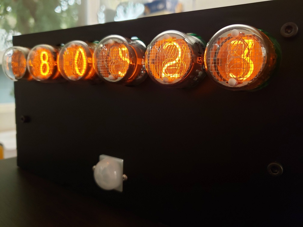
The clock from an odd angle 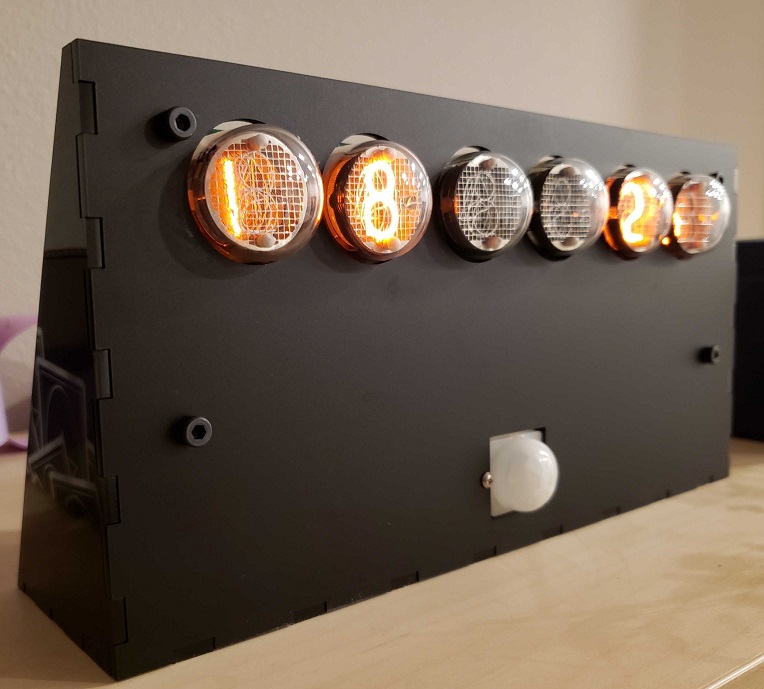
The full enclosure, with the tubes recessed a little bit more using 20mm standoffs 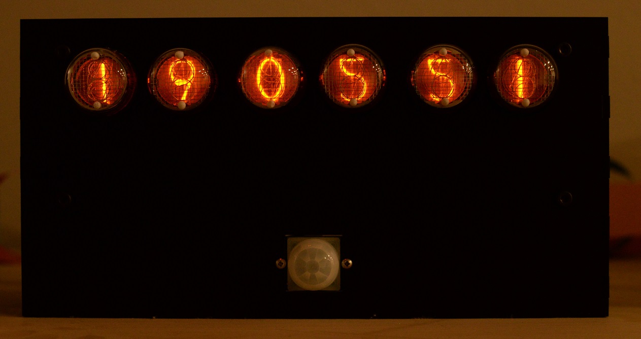
Finished clock showing the time (dark image so you can better see the glow of the tubes)
The clock shows the time, the internal temperature, the external temperature (based on querying OpenWeatherMap API with the right city code), and the AQI (air quality index using the AirNow API – a good idea for us in the west coast of the US who happen to be experiencing a lot of smoke in the air!). Right now I’ve got it alternating between the time, the internal and external temperatures (in one screen), and the AQI. The temperature units can be set to Celsius or Fahrenheit. Right now I cycle between these three “screens” every 20 seconds.
Time (HHMMSS) 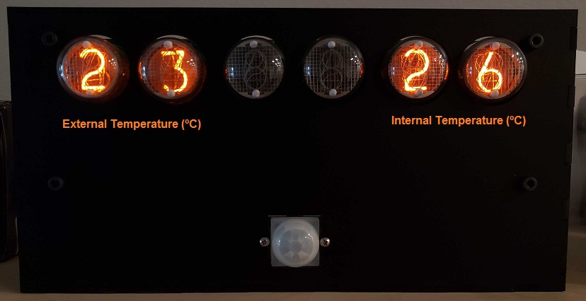
Temperatures 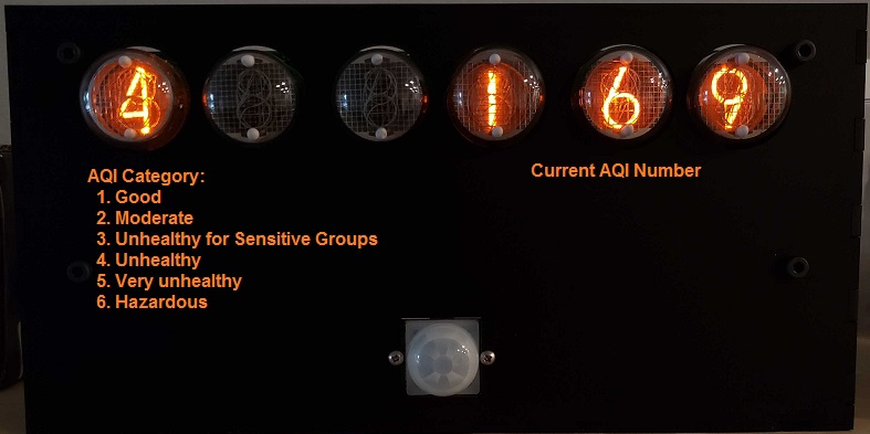
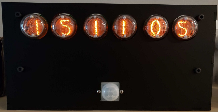
AQI (there was smoke this day!)
The PIR sensor is working well, too! I tuned the time it would have to go without seeing motion to fall asleep to a minute; this seems to work well because it’s enough time to cycle through all three screens and because I put the clock in a rather central location where it’s easy to wake it up by waving at it. The sensor has a 7m range in a 120 degree cone, which turns out to be just about perfect. I was having issues making it work initially and then I realized that I was giving it a 3.3V supply when it wanted to be connected to 5V – oops! In my defense, it specs 3-5V on the Adafruit website, but then there’s a little bit of text saying that if you want lower voltages to work you have to bypass the regulator on the PIR sensor board which I completely missed. It was easier to connect it directly to 5V instead, so I went ahead and changed the wiring to make that work. I’ll clean up the code a little bit more, edit my code post from last week, and post it there.
The project is more or less “done” now, but I’ll do a couple more review posts where we’ll look at reducing the cost of the whole product as well as making it easier to put together. Specifically, I’d like to:
- Improve the nixie footprints by rotating them clockwise slightly and make all of the holes significantly larger; this should allow the person soldering the tubes to rotate them in position and then solder them.
- Move the power supply onto the main board
- Remove the 40pin ribbon cable and allow a RPi Zero W to be directly connected instead (via a 90 degree header). Margaret has one that I can try to make sure it works OK (I can’t think of why it wouldn’t)
- Clean up and fix a few things on the PCB
- Try out multiplexing the tubes; if this looks good, I’ll do so on the final clock to reduce the number of necessary IOs. That will allow me to add a SPI/I2C temperature sensor to put on the board for a better sense of the room temperature.
I’ll also keep you updated on any new feature changes or other things I try, of course. One thing I’m thinking of doing is buying a Bluetooth temperature and humidity sensor like this one (you can bet that’s not an affiliate link!) and connecting it to the clock.