Scope Part 4 – Interrupt Example

Pushbutton schematic on the Discovery board

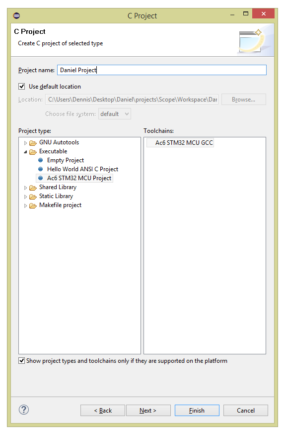
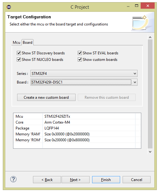
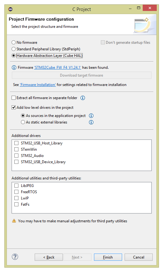
Today we’ll continue to play with the STM32F429-DISC1 eval board to learn more about the MCU and what it can do.

What’s an interrupt?

If your childhood was anything like like mine, your parents probably reprimanded you whenever you interrupted someone while they were talking. And if you were anything like me, you were interrupting because something occurred to you (likely as a response to whatever was being said by the interrupted person) and you wanted to say it before you forgot what it was, or maybe before it lost its impact.

Like us humans, the processor inside an MCU is in an environment with lots of action going on around it – buttons connected to it are being pressed, samples are coming in from an ADC, memory is filling up, timers are going off, and all sorts of other things are happening. There are two common ways of dealing with all this action – let’s review them real quick.

One approach, which as you’ll recall we used on the nixie clock project and is described here, is called polling. In a polling architecture, the processor checks on its subsystems “once in a while” to see what happened; the processor will set its own “checking periods” and is responsible for spending that time looking at each subsystem to see if it has anything to report to it. Some subsystems will have flags (bits that are set or cleared) that tell the processor that something happened since the last time that it checked; the error counters inside of Ethernet PHY chips are good examples of this – many error counters are self-clearing and the processor is expected to check them every once in a while. Other subsystems are not this smart – GPIO pins connected to buttons are either high or low, and if you’re not polling quickly enough you might just miss something that happened (e.g. you may only register one button press if there were two quick button presses in succession). Polling has fallen out of favor because, although it is simpler from an architecture, “wrapping your head around it” point of view, it is also more processor intensive. This is because the processor can’t be in “sleep mode” as much, as it has to constantly be waking itself up to check all the subsystems. In a battery-powered product, for example, you’d ideally like the processor to be asleep as much as possible, waking up only when absolutely necessary to deal with something that’s happened (like a button press).

This is where the second approach comes in, and that’s interrupts. Most processors have an interrupt controller built in to it, and that interrupt controller is connected to a wide variety of interrupt sources (both internal and external to the MCU). Here’s some examples:

  • GPIO pins connected to external devices (control signals, buttons/keypads, etc.)
  • Internal timers that can be configured to generate an interrupt every so often
  • Specific bits inside of registers that indicate various states for internal subsystems (e.g. a “half-full flag” inside a FIFO memory telling you that it’s now half full, a “link bit” inside an Ethernet PHY that tells you that a cable was plugged-in, an “enumeration complete” bit inside a USB or PCIe controller register that tells you a new device was hooked-up)
  • And more!

You have to write code to set up the interrupts – this means you want the interrupt controller to pay attention to the interrupts you specify in particular (the controller will typically ignore all sources by default). You can configure specific details about the interrupt source – like whether you want it to interrupt when the GPIO pin goes high only, or low only, or both when it goes high and low (for an edge-triggered interrupt). Then you register an interrupt handler function, which is the function that gets called whenever an interrupt of that type is received. Finally, you assign a priority to the interrupt – this is important because some interrupts will fire when you’re halfway through dealing with an interrupt, and in some cases you want to set that aside for a moment, deal with the new interrupt first, and come back to the old interrupt. And in other cases you most certainly do not want to do that.

Here’s a short example of why the priority is important. Let’s say we have two interrupt sources, one is connected to GPIO pin 0 of bank A, which is a push-button, and the other is an internal timer which we configured to fire every 10 ms to keep track of time. The interrupt handler for the button increments a variable in the code which represents how may times the button has been pushed. The interrupt handler for the timer adds 10ms to a variable which represents a supposedly accurate counter of how long it has been since the program started. The board has a display which shows both the time since the program started and the button-press counter. In this simple example, we’d like to have the timer interrupt have higher priority than the button interrupt because we’d like the time variable to be as accurate as possible. It doesn’t hurt anything if it takes a few extra milliseconds to update the button counter because the program was in the middle of doing that when the timer interrupt arrived. However, if we wait for the button interrupt to finish first (if they have equal priorities or if the timer priority is lower), then we’ll have an inaccurate time variable for the rest of the program’s length!

The important thing to keep in mind with interrupts is that we’re handing over the control of when the code gets called to the processor. When we write code for a polling-based architecture, we know exactly when and how often each subsystem gets polled (as a consequence, we might be responsible for writing the code poorly so we end up missing some events, but we still know when the checks happen). With interrupts, we write code that ends up looking a little more disjointed – instead of our main loop being a step-by-step procedure where we, for example, check a button, increment at timer variable, and write these two to the display, all we do in it is write the variables to the display and call it good; instead, somewhere else in the code there’s these two functions that look like they never get called from the main loop but are responsible for incrementing the variables. The processor is then responsible for bringing these two pieces of code together so that they do what we want them to do. Priority, masking, and some other things that we set up at the beginning of the program tells the processor how to do so to get the behavior that we want from the program.

A simple example

In this example we’ll set up an interrupt on the eval board’s blue push-button switch (the black one is a reset button, so we can’t use it in the code) that will toggle the LED on and off. Here’s the schematic for it:

Pushbutton schematic on the Discovery board

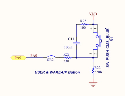
Note that the button is already debounced in hardware (via R25, C11, and R23) and the signal goes high when the button is pushed. It is connected to pin 0 of GPIO bank A. You’ll remember from the previous post that the green LED is connected to pin 13 of GPIO bank G. So here’s what we have to do to get the behavior we want:

  • Initialize GPIO bank G as we did before (to output on both the green and red LED)
  • Write an interrupt handler that toggles the LED pin (that’s all it has to do, ST’s code deals with clearing the interrupt and all the other “gritty embedded stuff” for you)
  • Initialize GPIO bank as an input with interrupt capability on pin 0. We’ll set it up so it’s edge-triggered when the signal transitions from low to high. The priority can be almost anything since it’s the only interrupt we’ll write; let’s keep it low to make sure nothing else breaks. Finally, we have to tell the processor that the function we wrote above is the interrupt handler for this interrupt.
  • That’s it! The while loop can just be an infinite loop that does nothing so that the program keeps running rather than just ending.

You can go ahead and write a program like we did in part 3 of the series. You can copy the clock configuration (SystemClock_Config) and error handler (Error_Handler) functions from there. Here’s our main loop, which will be very similar to the one from that post:

#include "stm32f4xx.h"
#include "stm32f429xx.h"
#include "stm32f4xx_hal_gpio.h"
#include "stm32f4xx_hal.h"
#include "stm32f4xx_hal_exti.h"
#include "stm32f4xx_it.h"

static void SystemClock_Config(void);
static void Error_Handler(void);
static void EXTILine0_Config(void);

int main(void)
{
    // Initialize the hardware abstraction layer libraries
    HAL_Init();
    __HAL_RCC_GPIOG_CLK_ENABLE();

    GPIO_InitTypeDef g = {GPIO_PIN_13 | GPIO_PIN_14, GPIO_MODE_OUTPUT_PP, GPIO_NOPULL, GPIO_SPEED_FREQ_LOW};
    HAL_GPIO_Init(GPIOG, &g);

    /* Configure the system clock to 180 MHz */
    SystemClock_Config();

    /* Configure EXTI Line0 (connected to PA0 pin) in interrupt mode */
    EXTILine0_Config();

    while (1) {

    }
}

Note that the main difference is that we now have a EXTILine0_Config() function which will configure an external interrupt (I guess that’s what “EXTI” is) on line 0 (the button) of GPIO bank A. That looks like this:

/**
  * @brief  Configures EXTI Line0 (connected to PA0 pin) in interrupt mode
  * @param  None
  * @retval None
  */
static void EXTILine0_Config(void)
{
  GPIO_InitTypeDef   GPIO_InitStructure;

  /* Enable GPIOA clock */
  __HAL_RCC_GPIOA_CLK_ENABLE();

  /* Configure PA0 pin as input floating */
  GPIO_InitStructure.Mode = GPIO_MODE_IT_RISING;
  GPIO_InitStructure.Pull = GPIO_NOPULL;
  GPIO_InitStructure.Pin = GPIO_PIN_0;
  HAL_GPIO_Init(GPIOA, &GPIO_InitStructure);

  /* Set EXTI Line0 Interrupt to the lowest priority and enable the interrupt */
  HAL_NVIC_SetPriority(EXTI0_IRQn, 2, 0);
  HAL_NVIC_EnableIRQ(EXTI0_IRQn);
}

A lot of this looks the same as the GPIO bank G initialization. Note that the “mode” parameter of the structure is now set to GPIO_MODE_IT_RISING, which will be an input that issues an interrupt on a rising edge. Finally, we set the priority to 2 (on a scale from 0 to 15, where 0 and 1 are really low priority events we shouldn’t mess with) and the subpriority to 0 (I’m not sure what that is yet, if we’re being honest), and the interrupt (often shortened to “IRQ”) is enabled. A few other things to note – internally, all the GPIO banks are connected together, so that all pin 0s (of bank A, bank B, all the way to bank G) can only issue EXTI0_IRQn interrupts. That’s something we’re going to have to keep in mind. That’s why pin 0 of bank A (the one that the button is connected to) corresponds to EXTI0_IRQn. It also means that ST has configured the code to have a specific interrupt handler already – EXTI0_IRQn has the interrupt handler function HAL_GPIO_EXTI_Callback automatically registered to it, so we don’t have to do anything except write this function, which I reproduced below. Since there’s only one interrupt handler for all EXTI events (i.e. EXTI0-EXTI15), the function has an argument which indicates which pin(s) triggered the interrupt. In this case, all we have to do with that is check that it corresponds to the pin to which the button is connected (GPIO_PIN_0):

/**
  * @brief EXTI line detection callbacks
  * @param GPIO_Pin: Specifies the pins connected EXTI line
  * @retval None
  */
void HAL_GPIO_EXTI_Callback(uint16_t GPIO_Pin)
{
    if (GPIO_Pin == GPIO_PIN_0) {
        HAL_GPIO_TogglePin(GPIOG, GPIO_PIN_13);
    }
}

That should be all there is to it! You can build and run the program like we did in part 3 of the series, and you should see behavior like this:

Scope Part 3 – Getting Started with the Evaluation Board

Scope Part 3 – Getting Started with the Evaluation Board

Do I need to get an evaluation board?

It’s up to you to determine whether to get an eval board or not; I’m choosing to get one so that I can begin my software development without having to wait for my board design and the fabrication of the boards. Additionally, I anticipate that I’ll make quite a few mistakes on the first revision of the board, so it’ll be very helpful to have a working board to compare against when something isn’t going as intended – it’ll help suss out whether the issue is software/configuration related or if the custom hardware is problematic. If you’re reading this in the future and I already have a “working” board design that you can make, I think the evaluation board loses some of its value. However, consider that if you don’t get one, you’ll have to get a $22 ST-Link Programmer; the cost of the evaluation board is $32 and it can be used to program another board, so I think it could be a pretty worth it for just $10.

I am likely going to be focusing the next few posts on the work I’m doing with the STM32F429I-DISC1 board, so you’ll have to settle for just reading the articles if you’re not getting the board (rather than replicating the steps on your own evaluation board). Most of the topics will apply directly to work we’ll do on the custom board, however, so the posts will still add some value!

Setup

I ordered my board from one of the five distributors on the “Sample & Buy” tab of the page above. It arrived in a plastic clam-shell package without a USB Type-A to Mini-B USB cable, but I have a few those of handy; you may have to order one if you don’t have any available. The packaging advertises several “development toolchains”, including: Keil MDK, IAR, SW4STM32, and ARM mbed online. I did a little research and, of these, I think Keil is by far the most used toolchain for this processor, but the free version of Keil limits your code size to 32KB. Going beyond this costs quite a lot; I requested a quote and it seems like the MDK version of Keil costs as much as $6600 per user for a perpetual license, or $2600 for a single year! I don’t know whether I’ll need more than 32KB of code space or not, but I’m not in favor of this code-limiting model. So I decided to work with SW4STM32 (System Workbench for STM32) which is free, open-source, and it only requires you to make an account on their page. It’s built on top of Eclipse (also open-source), so you’ll have to download that, too, following instructions on this page to install from within Eclipse (I downloaded Eclipse 2019-12) after you register for an account.

Quick introduction to the environment

After you’ve got it downloaded and installed, let’s make a new project. Click on File->New->Project and select C Project. If everything installed properly, you should have an option under “Executable” on the left that is Ac6 STM32 MCU Project; select that, give it a name, and hit next and next again on the next screen. When you get to the Target Configuration Screen, select STM32F4 on the Series drop-down and STM32F429I-DISC1 on the Board drop-down and hit Next. Finally, select “Hardware Abstraction Layer (Cube HAL)” in the Project Firmware configuration and hit Finish. This process is detailed in the images below (please click on each of them for the full-sized equivalent).

The Hardware Abstraction Layer libraries are a set of header files that, you guessed it, help you use the hardware built-in to the MCU. The Standard Peripheral Library used to be the de facto standard, and you’ll still see a lot of examples using them out on the web, but they have been deprecated in favor of the HAL libraries, so we will be using those instead.

After completing the above steps, you should have a project folder on the far left screen in Eclipse with the name you typed in. If we open that folder open we’ll see some subfolders of interest:

  • Binaries – This holds the file(s) that actually get written to the MCU (called an “.elf” file)
  • Includes – Standard C include files
  • HAL_Driver – Manuals, include files, and source files for the HAL libraries. We’ll be browsing these a lot.
  • src – Your own code
  • inc – Your own include files
  • Utilities – “Bonus” content, including a folder for the specific eval board we’re using (STM32F429I-Discovery) that has specific header files and source code for how the board is connected (for instance, we can refer to the first LED as LED0 rather than “drive GPIO pin 13 of IO block G”)
  • Among others

The HAL files are fairly well documented. For instance, here’s a set of comments detailed how to set up the GPIO in stm32f4xx_hal_gpio.c:

/*  
                    ##### How to use this driver #####
  ==============================================================================  
  [..]
    (#) Enable the GPIO AHB clock using the following function: __HAL_RCC_GPIOx_CLK_ENABLE(). 

    (#) Configure the GPIO pin(s) using HAL_GPIO_Init().
        (++) Configure the IO mode using "Mode" member from GPIO_InitTypeDef structure
        (++) Activate Pull-up, Pull-down resistor using "Pull" member from GPIO_InitTypeDef 
             structure.
        (++) In case of Output or alternate function mode selection: the speed is 
             configured through "Speed" member from GPIO_InitTypeDef structure.
        (++) In alternate mode is selection, the alternate function connected to the IO
             is configured through "Alternate" member from GPIO_InitTypeDef structure.
        (++) Analog mode is required when a pin is to be used as ADC channel 
             or DAC output.
        (++) In case of external interrupt/event selection the "Mode" member from 
             GPIO_InitTypeDef structure select the type (interrupt or event) and 
             the corresponding trigger event (rising or falling or both).

    (#) In case of external interrupt/event mode selection, configure NVIC IRQ priority 
        mapped to the EXTI line using HAL_NVIC_SetPriority() and enable it using
        HAL_NVIC_EnableIRQ().
         
    (#) To get the level of a pin configured in input mode use HAL_GPIO_ReadPin().
            
    (#) To set/reset the level of a pin configured in output mode use 
        HAL_GPIO_WritePin()/HAL_GPIO_TogglePin().
    
    (#) To lock pin configuration until next reset use HAL_GPIO_LockPin().

                 
    (#) During and just after reset, the alternate functions are not 
        active and the GPIO pins are configured in input floating mode (except JTAG
        pins).
  
    (#) The LSE oscillator pins OSC32_IN and OSC32_OUT can be used as general purpose 
        (PC14 and PC15, respectively) when the LSE oscillator is off. The LSE has 
        priority over the GPIO function.
  
    (#) The HSE oscillator pins OSC_IN/OSC_OUT can be used as 
        general purpose PH0 and PH1, respectively, when the HSE oscillator is off. 
        The HSE has priority over the GPIO function.
*/

Let’s blink an LED!

This is basically the “Hello World” equivalent of embedded systems, so let’s get right to it! First off, let’s take a quick peek at the schematic for the board we’re working with. You’ll see on page 6 that we have two LEDs, one green and one red; the green LED is connected to pin 13 of GPIO bank G (that’s on page 5) through a 510 ohm resistor. The red LED is connected to pin 14 of GPIO bank G through a 680 ohm resistor. For this short example, let’s ignore the fancy “Utilities” libraries and use this information from the schematic. So this is what we need in order to create a successful program:

  • Initialize the system clock (we can technically rely on whatever is the default, but let’s try to start off on the right foot).
  • Initialize all the HAL stuff and GPIO bank G where the LED is.
  • Initialize the pin connected to the LED
  • Drive the LED high and low, with a delay in between of, say, half a second.

Here are the includes we will need:

  • stm32f4xx.h – General STM32F4 MCU family library
  • stm32f429.h – LIbrary more specific to the STM32F429 MCU
  • stm32f4xx_hal_gpio.h – GPIO library
  • stm32f4xx_hal.h – Another general STM32F4 library, this time specific to HAL

Let’s go ahead and dive into the code for the main function for this quick demo program:

#include "stm32f4xx.h"
#include "stm32f429xx.h"
#include "stm32f4xx_hal_gpio.h"
#include "stm32f4xx_hal.h"

static void SystemClock_Config(void);
void Error_Handler();

int main(void)
{
    // Initialize the hardware abstraction layer libraries
    HAL_Init();

    // Route the clock to GPIO Bank G 
    __HAL_RCC_GPIOG_CLK_ENABLE();

    /* Set up the GPIO:
           1. Using pins 13 and 14
           2. Push-pull (rather than open drain)
           3. No pull-down or pull-up
           4. Low frequency (nothing fancy here!)
    */
    GPIO_InitTypeDef g = {GPIO_PIN_13 | GPIO_PIN_14, GPIO_MODE_OUTPUT_PP, GPIO_NOPULL, GPIO_SPEED_FREQ_LOW};
    HAL_GPIO_Init(GPIOG, &g);

    /* Configure the system clock to 180 MHz */
    SystemClock_Config();

    while (1) {
        // Blink the green LED and wait 500ms
        HAL_GPIO_TogglePin(GPIOG, GPIO_PIN_13);
        HAL_Delay(500);
    }
}

As we talked about before, the code above pretty obviously initializes the HAL modules, the GPIO bank we want (bank G), sets up the system clock, and starts blinking the LED. Let’s dig into the GPIO_InitTypeDef structure a little more. The ST Micro libraries follow this module very closely everywhere as far as I can tell – the module is initialized by passing a initialization function a pointer to a structure with all the relavant bits (pun fully intended) you want initialized. In this case, the structure is defined in TODO and reproduced below:

/** 
  * @brief GPIO Init structure definition  
  */ 
typedef struct
{
  uint32_t Pin;       /*!< Specifies the GPIO pins to be configured.
                           This parameter can be any value of @ref GPIO_pins_define */

  uint32_t Mode;      /*!< Specifies the operating mode for the selected pins.
                           This parameter can be a value of @ref GPIO_mode_define */

  uint32_t Pull;      /*!< Specifies the Pull-up or Pull-Down activation for the selected pins.
                           This parameter can be a value of @ref GPIO_pull_define */

  uint32_t Speed;     /*!< Specifies the speed for the selected pins.
                           This parameter can be a value of @ref GPIO_speed_define */

  uint32_t Alternate;  /*!< Peripheral to be connected to the selected pins. 
                            This parameter can be a value of @ref GPIO_Alternate_function_selection */
}GPIO_InitTypeDef;

// And here's the #defines we can use with the above!

/** @defgroup GPIO_pins_define GPIO pins define
  * @{
  */
#define GPIO_PIN_0                 ((uint16_t)0x0001)  /* Pin 0 selected    */
#define GPIO_PIN_1                 ((uint16_t)0x0002)  /* Pin 1 selected    */
#define GPIO_PIN_2                 ((uint16_t)0x0004)  /* Pin 2 selected    */
#define GPIO_PIN_3                 ((uint16_t)0x0008)  /* Pin 3 selected    */
#define GPIO_PIN_4                 ((uint16_t)0x0010)  /* Pin 4 selected    */
#define GPIO_PIN_5                 ((uint16_t)0x0020)  /* Pin 5 selected    */
#define GPIO_PIN_6                 ((uint16_t)0x0040)  /* Pin 6 selected    */
#define GPIO_PIN_7                 ((uint16_t)0x0080)  /* Pin 7 selected    */
#define GPIO_PIN_8                 ((uint16_t)0x0100)  /* Pin 8 selected    */
#define GPIO_PIN_9                 ((uint16_t)0x0200)  /* Pin 9 selected    */
#define GPIO_PIN_10                ((uint16_t)0x0400)  /* Pin 10 selected   */
#define GPIO_PIN_11                ((uint16_t)0x0800)  /* Pin 11 selected   */
#define GPIO_PIN_12                ((uint16_t)0x1000)  /* Pin 12 selected   */
#define GPIO_PIN_13                ((uint16_t)0x2000)  /* Pin 13 selected   */
#define GPIO_PIN_14                ((uint16_t)0x4000)  /* Pin 14 selected   */
#define GPIO_PIN_15                ((uint16_t)0x8000)  /* Pin 15 selected   */
#define GPIO_PIN_All               ((uint16_t)0xFFFF)  /* All pins selected */
/**
  * @}
  */

/** @defgroup GPIO_mode_define GPIO mode define
  * @brief GPIO Configuration Mode 
  *        Elements values convention: 0xX0yz00YZ
  *           - X  : GPIO mode or EXTI Mode
  *           - y  : External IT or Event trigger detection 
  *           - z  : IO configuration on External IT or Event
  *           - Y  : Output type (Push Pull or Open Drain)
  *           - Z  : IO Direction mode (Input, Output, Alternate or Analog)
  * @{
  */ 
#define  GPIO_MODE_INPUT                        0x00000000U   /*!< Input Floating Mode                   */
#define  GPIO_MODE_OUTPUT_PP                    0x00000001U   /*!< Output Push Pull Mode                 */
#define  GPIO_MODE_OUTPUT_OD                    0x00000011U   /*!< Output Open Drain Mode                */
#define  GPIO_MODE_AF_PP                        0x00000002U   /*!< Alternate Function Push Pull Mode     */
#define  GPIO_MODE_AF_OD                        0x00000012U   /*!< Alternate Function Open Drain Mode    */

#define  GPIO_MODE_ANALOG                       0x00000003U   /*!< Analog Mode  */
    
#define  GPIO_MODE_IT_RISING                    0x10110000U   /*!< External Interrupt Mode with Rising edge trigger detection          */
#define  GPIO_MODE_IT_FALLING                   0x10210000U   /*!< External Interrupt Mode with Falling edge trigger detection         */
#define  GPIO_MODE_IT_RISING_FALLING            0x10310000U   /*!< External Interrupt Mode with Rising/Falling edge trigger detection  */
 
#define  GPIO_MODE_EVT_RISING                   0x10120000U   /*!< External Event Mode with Rising edge trigger detection               */
#define  GPIO_MODE_EVT_FALLING                  0x10220000U   /*!< External Event Mode with Falling edge trigger detection              */
#define  GPIO_MODE_EVT_RISING_FALLING           0x10320000U   /*!< External Event Mode with Rising/Falling edge trigger detection       */
/**
  * @}
  */
/** @defgroup GPIO_speed_define  GPIO speed define
  * @brief GPIO Output Maximum frequency
  * @{
  */
#define  GPIO_SPEED_FREQ_LOW         0x00000000U  /*!< IO works at 2 MHz, please refer to the product datasheet */
#define  GPIO_SPEED_FREQ_MEDIUM      0x00000001U  /*!< range 12,5 MHz to 50 MHz, please refer to the product datasheet */
#define  GPIO_SPEED_FREQ_HIGH        0x00000002U  /*!< range 25 MHz to 100 MHz, please refer to the product datasheet  */
#define  GPIO_SPEED_FREQ_VERY_HIGH   0x00000003U  /*!< range 50 MHz to 200 MHz, please refer to the product datasheet  */
/**
  * @}
  */

 /** @defgroup GPIO_pull_define GPIO pull define
   * @brief GPIO Pull-Up or Pull-Down Activation
   * @{
   */  
#define  GPIO_NOPULL        0x00000000U   /*!< No Pull-up or Pull-down activation  */
#define  GPIO_PULLUP        0x00000001U   /*!< Pull-up activation                  */
#define  GPIO_PULLDOWN      0x00000002U   /*!< Pull-down activation                */
/**
  * @}
  */

The code uses two helper functions, static void SystemClock_Config(void) (sets up the system clock) and void Error_Handler() (acts on errors on initialization of the system clock). Unfortunately, since we can’t do a print or anything like that, all the error handler will do for now is turn on the red LED and hang the program. Here’s the code for this:

/**
  * @brief  System Clock Configuration
  *         The system Clock is configured as follow :
  *            System Clock source            = PLL (HSE)
  *            SYSCLK(Hz)                     = 180000000
  *            HCLK(Hz)                       = 180000000
  *            AHB Prescaler                  = 1
  *            APB1 Prescaler                 = 4
  *            APB2 Prescaler                 = 2
  *            HSE Frequency(Hz)              = 8000000
  *            PLL_M                          = 8
  *            PLL_N                          = 360
  *            PLL_P                          = 2
  *            PLL_Q                          = 7
  *            VDD(V)                         = 3.3
  *            Main regulator output voltage  = Scale1 mode
  *            Flash Latency(WS)              = 5
  * @param  None
  * @retval None
  */
static void SystemClock_Config(void)
{
  RCC_ClkInitTypeDef RCC_ClkInitStruct;
  RCC_OscInitTypeDef RCC_OscInitStruct;

  /* Enable Power Control clock */
  __HAL_RCC_PWR_CLK_ENABLE();

  /* The voltage scaling allows optimizing the power consumption when the device is
     clocked below the maximum system frequency, to update the voltage scaling value
     regarding system frequency refer to product datasheet.  */
  __HAL_PWR_VOLTAGESCALING_CONFIG(PWR_REGULATOR_VOLTAGE_SCALE1);

  /* Enable HSE Oscillator and activate PLL with HSE as source */
  RCC_OscInitStruct.OscillatorType = RCC_OSCILLATORTYPE_HSE;
  RCC_OscInitStruct.HSEState = RCC_HSE_ON;
  RCC_OscInitStruct.PLL.PLLState = RCC_PLL_ON;
  RCC_OscInitStruct.PLL.PLLSource = RCC_PLLSOURCE_HSE;
  RCC_OscInitStruct.PLL.PLLM = 8;
  RCC_OscInitStruct.PLL.PLLN = 360;
  RCC_OscInitStruct.PLL.PLLP = RCC_PLLP_DIV2;
  RCC_OscInitStruct.PLL.PLLQ = 7;
  if(HAL_RCC_OscConfig(&RCC_OscInitStruct) != HAL_OK)
  {
    Error_Handler();
  }

  /* Activate the Over-Drive mode */
  HAL_PWREx_EnableOverDrive();

  /* Select PLL as system clock source and configure the HCLK, PCLK1 and PCLK2
     clocks dividers */
  RCC_ClkInitStruct.ClockType = (RCC_CLOCKTYPE_SYSCLK | RCC_CLOCKTYPE_HCLK | RCC_CLOCKTYPE_PCLK1 | RCC_CLOCKTYPE_PCLK2);
  RCC_ClkInitStruct.SYSCLKSource = RCC_SYSCLKSOURCE_PLLCLK;
  RCC_ClkInitStruct.AHBCLKDivider = RCC_SYSCLK_DIV1;
  RCC_ClkInitStruct.APB1CLKDivider = RCC_HCLK_DIV4;
  RCC_ClkInitStruct.APB2CLKDivider = RCC_HCLK_DIV2;
  if(HAL_RCC_ClockConfig(&RCC_ClkInitStruct, FLASH_LATENCY_5) != HAL_OK)
  {
    Error_Handler();
  }
}

void Error_Handler() {
    // Oops. Bad stuff happened! Let's turn on the red LED.
    HAL_GPIO_WritePin(GPIOG, GPIO_PIN_13, GPIO_PIN_SET);

    while (1) { }
}

Don’t worry too much about SystemClock_Config(void) yet – it’s a copy-pasted version of ST’s standard clock configuration function for running the system at 180 MHz. We obviously don’t need to run the processor at it’s maximum clock for blinking an LED, but we’ll likely end up running it at this frequency in the finished product. We will dive more deeply into how that code gets generated inside the STM32F4CubeMX software in a few posts.

That’s it for this post! After you put the code above in one file (main.c) and build (using the hammer icon), you can program the board by right clicking on the project (the folder) and selecting Target -> Program Chip. You can tell the IDE to reset the board and you should see the green LED start blinking right away like in the below animation!

See you next time for some fun running the demos ST Micro includes with their libraries on this evaluation board and another short example!.

Scope Part 2 – Let’s Pick a Microcontroller

Scope Part 2 – Let’s Pick a Microcontroller

Picking out a microcontroller is a bit of an arcane art; the requirements are often hazy, the process is full of pitfalls, everyone’s got a different opinion, and it usually feels like the only way to succeed is to have done it before and gotten it to work. This is so much the case that people tend to stick with whatever manufacturer/part family they’ve worked with before – check out the (often very fervent) discussions between the two biggest camps for hobbyists, the Atmel AVR group (if you’ve heard of Arduino, this is a superset of that) and the Microchip PIC group, and that’s now the same manufacturer (Microchip acquired Atmel in 2016)!

I’ve picked out a processor already (yes, you guessed it, it’s something I’ve used before), but let’s walk through some of the considerations here, both for this project in particular as well as any project in general. But first – what is a microcontroller? What’s a microprocessor? What’s the difference?

The “micro” in microprocessor just means small and, as far as I know, it’s an arbitrary designation on some processors and controllers. In fact, while I’ve heard of “just processors” (no micro) like the many parts Intel makes for desktops and laptops, I’ve yet to hear of “just controllers.” From a very high-level point of view, a processor (micro or not) is a chip that will run code – it has several “subblocks” inside of it that help it do it, like a small amount of memory (L1/L2 cache, registers), the Arithmetic Logic Unit (ALU – how the processor “does math”), hook-ups for external memory and other interfaces, and many other things that I’ve since forgotten. A microcontroller is a chip that has a microprocessor inside of it as well as other internal blocks, the nature of which depend on the specific controller (some examples: ADCs, DACs, more internal memory, LCD display controller, analog comparators, …). Having these blocks to hook up to can be quite handy, as we’ll see in our project.

High-Level Considerations

Here’s a list of some common microcontroller specifications to get us started:

  • “Speed” – How “quickly” the internal microprocessor runs – typically measured in instructions per second (or more coarsely by the CPU clock)
  • Internal memory – How much ROM and RAM the microcontroller has internally in its caches as well as for general use – if it has enough of it, we might get away with not having an external memory chip
  • “Modules”/interfaces – Internal ‘components’ the microcontroller has, like ADCs, DACs, etc. or interface hook-ups like supporting Ethernet or USB
  • Architecture – This is a high-level way of describing how the microcontroller is “organized” inside (in terms of how things are connected internally and how time intensive it is to perform certain tasks, like reading a byte from memory). I include “how many bits” are in the processor in here as well, for example, a 32 bit ARM processor vs a 16 bit MIPS processor. This also determines the maximum amount of memory the microcontroller can interface with.
  • Power usage – How much power the chip consumes (this is usually specified under “normal load”, in some sort of “sleep” or “suspended” mode, and under “maximum load”). This is a very important spec. for battery-powered products that want to last as long as possible before needing to be recharged.
  • Footprint – What the chip pinout looks like physically – this affects the layout as well as the solderability (assuming we’re putting the board together ourselves)
  • “Tools” – This list is very important (perhaps the most important consideration if we’re working on a project by ourselves)
    • Programmer – Do we need to buy a programmer that connects to a computer to “write” the code to the chip? How easy is it do so?
    • Utilities – Does the manufacturer provide header files and basic functions for each of the microcontroller “modules” or do we need to write everything ourselves from the datasheet?
    • Evaluation board – Does the manufacturer provide a design (schematic and layout files as well as a board you can sample or buy) that they’ve “blessed” as being good? It can be incredibly useful to have a model to emulate.
    • Websites – Is this chip often used by other hobbyists? Can we find helpful websites with examples and/or forums where we can ask questions if we get stuck with something? This is a very important consideration, especially if we’re planning on doing this project alone (that is, without the help of a friend that’s done this or something very similar with the same microcontroller).

Let’s think about what requirements we need for this project in particular, in the same order as above (if you haven’t read part 1 of the series, consider giving it a quick glance before continuing):

  • Speed – There’s nothing from the design point of view that requires the microcontroller to be extraordinarily “fast” if we implemented the sampling hardware as we discussed in part 1 of the series. That said, we’d still like to processes those samples quickly once we’ve gotten a trigger and send them off to the display to create a “responsive system”, and that’ll require some quick thinking. If our maximum sampling frequency is 50-60 MHz, let’s try to pick something at or above 100 Megainstructions Per Second (MIPS) to keep up with this. This is very much a number that I pulled out of nowhere (there’s nothing magical about “2 instructions per sample”), but consider that we don’t need to optimize for power consumption or anything else that would increase with the speed of our processor (other than cost), since this will just be a bench-top oscilloscope; so let’s see if we can find an affordable 100 MSPS chip to use.
  • Here’s a list of helpful modules:
    • TFT display controller – An internal module that generates the right clock signals for driving the LCD-TFT displays that are common in embedded systems. This is highly preferable to a much slower SPI-based (Serial Peripheral Interface, a very common interface in almost all controllers) display that we’d be forced to use without the built-in display controller.
    • Internal ADC – We’re not going to find very many internal ADCs that can sample at 50+ MSPS (yes, amazingly, some exceptions do exist). Even if the internal ADC is fast and everything we could ever want, we’re not going to find a microcontroller with an “oscilloscope triggering logic block” like what we discussed on part 1. However, an internal ADC (even if it is slow) will be useful for debugging and writing the code while we’re still working on our external sampling hardware. As I alluded to in the project page, we can also use the development board’s internal ADC to debug our oscilloscope design.
    • Internal DAC – It’d be nice to generate some analog signals on the development board that we can then look at with our scope to test it (for those of us who don’t own function generators).
    • Internal memory – This is more of a “wishlist” item, but ideally we have enough memory that we don’t need any external chips (except for the signal samples as we discussed in part 1 and the display memory)
    • Plenty (say, about 40) of IOs that we can break out into header pins for when we make mistakes
    • At least one of each SPI and I2C interface because we’re likely going to need them for something (even if it’s just for an on-board temperature sensor)
  • Architecture – I don’t think we have to be picky on this one. I’ve used (and liked) ARM processors in the past, but I’m happy to try something new, too. And we don’t have to worry about interfacing with large amounts of memory, either.
  • Power usage – We’re not running this off a coin cell battery, so we’re again not super picky; but it’d be nice if it didn’t heat up like bonkers. Let’s try to keep it at or below a Watt.
  • Footprint – Something we can solder without the use of a reflow oven or heat gun – this disqualifies all BGA or QFN packages, for example.
  • Tools
    • Programmer – I want to be able to program this from a computer’s USB port (please no RS-232 port requirement). If I have to buy a programmer, I’d like to spend less than $50 on it.
    • Utilities – I’ve started a project before with just a datasheet and written the assembly code to interface with all the registers. I’d rather not do that directly again, and I don’t think that would be the most instructive use of our time (maybe on another, smaller project). I want good header files and cross-platform support for writing and compiling the code. I’m OK with using a “manufacturer sanctioned” IDE to write the code so long as:
      1. I don’t have to pay for using the IDE
      2. The fact that I’m not paying for the IDE doesn’t restrict me (for example: can only compile projects <32KB in size; yes, I’m looking at you, Keil)
    • Yes, I want an evaluation board, and I plan to use it heavily for developing the initial code as well as debugging my own board.
    • Some amount of support would be nice for this project, but I think not crucial. It’s one of the only things on this list I’d be flexible compromising on.

So what are we going with?

I decided to use ST Micro’s STM32F429 (datasheet) microcontroller. I like the STM32F4 series quite a bit; I used several of these on a project at college where a group of us tried (and failed) to build an electric car. The MCU worked well, though! Here’s what it has going for it, in the same order as above:

  • 180MHz max CPU clock, 225 MIPS. We can get a lot done with this chip!
  • Helpful modules:
    • 1 or 2MB (depending on the exact model) of integrated Flash memory for storing code. Way more than what we need.
    • 256KB internal RAM – probably sufficient. How many variables do we need, anyway?
    • LCD TFT controller and parallel interface (this only comes with the STM32F429 version – the STM32F407 and STM32F427 MCUs are more general chips without the LCD stuff)
    • 3 12-bit, 2.4 MSPS ADCs – not bad at all for a debug tool; we can make two channel scope to debug our real scope.
    • 2 12-bit DACs – excellent
    • A bunch of IOs (how many exactly depends on which model you get, but at least 40 of them, given the smallest package is 100 pins)
    • SPI and I2C
  • 32-bit ARM processor and a good DMA controller to interface to external memory if we need it (we will at least need some SDRAM to store the data for the LCD pixels)
  • At 270mA max current draw, the total maximum power consumption is 3.3V * 0.27m = 0.9W, right about our target. But I don’t think we will hit this maximum number, as we won’t always be working the processor to its fullest.
  • The BGA packages are a no-go, but the LQFP packages are OK to hand-solder
  • Tools
    • The ST-Link programmer is just $20, but even better, the eval board comes with that functionality out of the box (you program it through a simple micro USB connector). And according to people online, we can rewire the eval board to program our own custom board! That’s great news.
    • ST provides extensive header files and examples for this family. For every module (e.g. for the display on the eval board), ST provides example code for interacting with it in one big package called STM32CubeF4. There is a free, open-source IDE called SW4STM32 built on top of Eclipse we can use on Windows or Linux for compiling, linking, and locating the code, and we can program the chip directly from there.
    • The eval board for this MCU is called 32F429-Discovery and it comes with a display and everything! To give you an idea of how relevant this board is our project, check out this video of a homemade scope project running on the eval board itself!
    • This family of processors has a decent following online. As an example, check out STM32F4-discovery. At the very least we will probably be able to get answers to our basic questions.

Curious for more?

Sorry for throwing a bunch of specs and text at your face. In the next few posts you’ll be able to see the microcontroller in action (I’ll walk you through how I set up my computer to program it and quite a few examples with it) and hopefully that’ll justify the choice far better than the wall of text above. It should also be a little more exciting.

However, if you somehow really enjoyed this and are interested in reading more on this subject, check out this excellent comparison of sub-dollar processors. If you’d like to dig more into the specifications above and what they mean in terms of how the processor works internally, consider going through this free book/online course on computer architecture and ARM assembly programming on Raspberry Pi. Finally, if you’ve really got a lot of time, you might want to read Michael Slater’s excellent (if slightly outdated as it is a “classic”) textbook Microprocessor-Based Design (to the best of my knowledge that is not an affiliate link, I recommend you get the cheapest used version you can!).