Another post, another PCB. Hopefully that’s not par for the course…
I just sent the Rev 1.1 PCBs off to fab. I made the following changes:
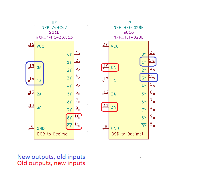
- Swapped out the 74HC42 decoders for HEF4028BT parts, to address the issue discussed in the previous post. This involved a fair amount of re-routing as the pinout was quite different.
- Changed the footprint for the nixie tubes and rotated them 180 degrees so that the board can be mounted right-side up on the enclosure
- Added screw terminal headers for connecting the PIR sensor and the switch to the board (they will both be mounted onto the enclosure itself, so they will need to wire into the board)
- Moved the BJTs closer to the nixie tubes to shorten the length of the 40-70V collector traces
- Grew the board’s width by 30mm and re-arranged the nixie tubes so that they’d be spaced a little further apart
- Changed the M3 mounting holes into M4 ones. I had the space and the M3 posts on my enclosure were looking a little fragile.
In parallel, I reworked one tube’s worth of the current board to work with the HEF4028BT to make sure that the interface between than and the RPi was OK (the part’s power pin is specified down to 3V, but the input high level is only spec’d when it’s powered off 5V, and it’s 3.5V) and that it wouldn’t have a problem driving the BJTs. It seems to have worked well. In order to make it work, I had to at least re-route two of the previous outputs to the Raspberry Pi and vice-versa, see below. This would ensure that inputs would still be connected to inputs and outputs would be connected to outputs. However, doing only this leaves the logic table very scrambled! I wrote down the options and “decoded” (pun fully intended) the logic.
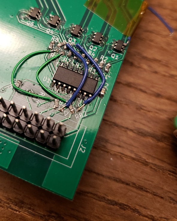
Here’s the min required input/output swap on the board. Thank goodness for series resistors!
I didn’t want to solder a nixie tube onto the board to test it since I’d need to de-solder it later (to put it on the new board) and that wouldn’t have been the most fun without clipping the leads. So I soldered a single digit (the “1”) up to a wire which I then hooked up to the tube with clips. You can see a picture of the full system in action below.
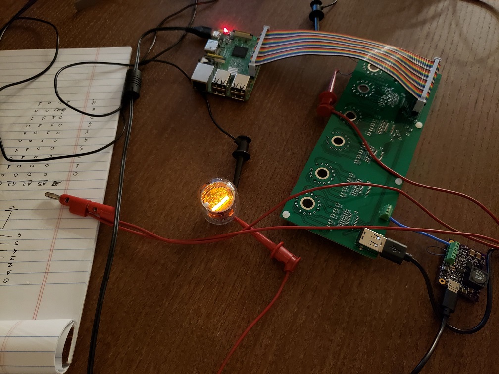
Full system wired and working together for the first time!
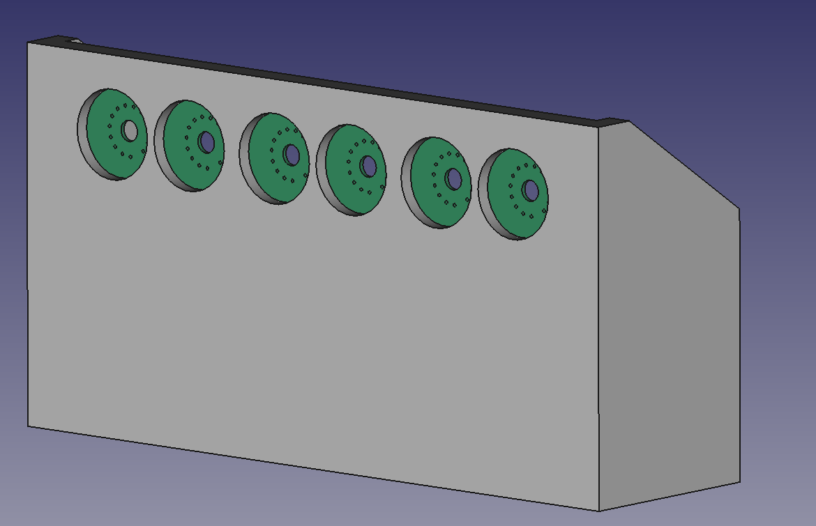
I’ve also scrapped the previous version of the enclosure (which had the board mounted upside down) and started over. Here’s some shots of the new enclosure design with the Raspberry Pi, power supply, and main board shown.

Front view 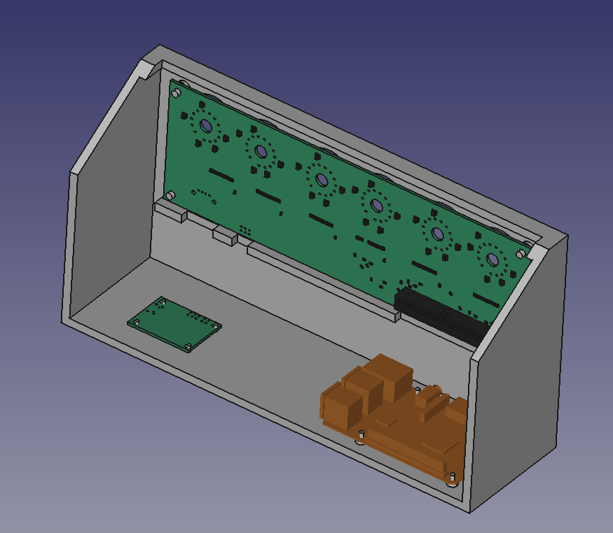
The brown board is the RPi 3 model, the small board is the 5V to 170V supply