It’s a new post in the series and this time there isn’t a new PCB! So there is hope after all…
I haven’t had much of a change to work on the electronics part of the project since the new board hasn’t arrived yet, so I’ve been mainly focusing on the enclosure design aspect. A friend of mine suggested looking more into manufacturing techniques before continuing, so I took his advice and decided I’d give laser cutting a go for my first prototype. I really like how the finished products look with this technique and it seemed cost effective for a larger design like this one.
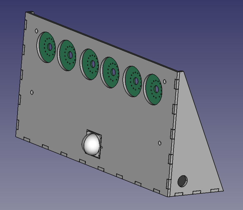
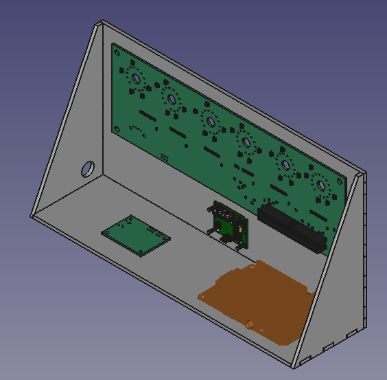
Since a laser cut enclosure is just a set of 2D shapes of fixed thickness, I could no longer have the small features I’d designed to hold the various boards in place. In order to deal with this, I added screw holes on the front face to hold up the main board and PIR sensor. I’m planning to have the screw heads on the front face, with the screws going through a small spacer, the boards, and then a nut on the other side. I have no plans for securing the RPi and supply boards to the bottom of the enclosure for now, but I might make a ledge or something like that on a future revision. Note the hole on the right side for a button!
I like the look of this “open air” enclosure for a prototype, so I might keep that going forward. My main concern for now is that the whole thing is going to want to tilt forwards as it’ll be top heavy because of the tubes. I may have to increase the size of the base or make it heavier going forward. For now I can always weight it down with something.