")
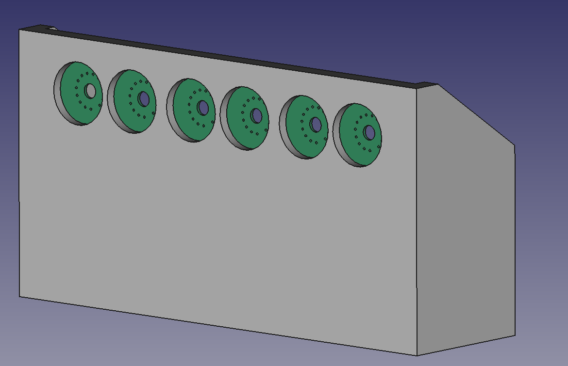
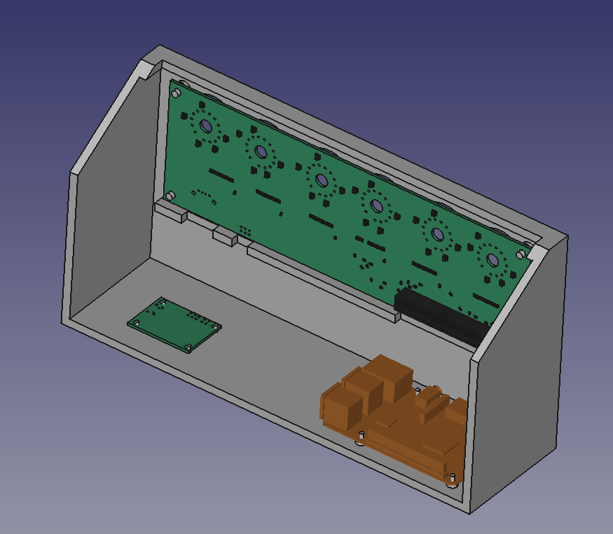
The first enclosure I’ve ever designed arrived a few days ago (I wonder if it still count as an enclosure if it has an open back, as it’s not fully enclosing anything)!
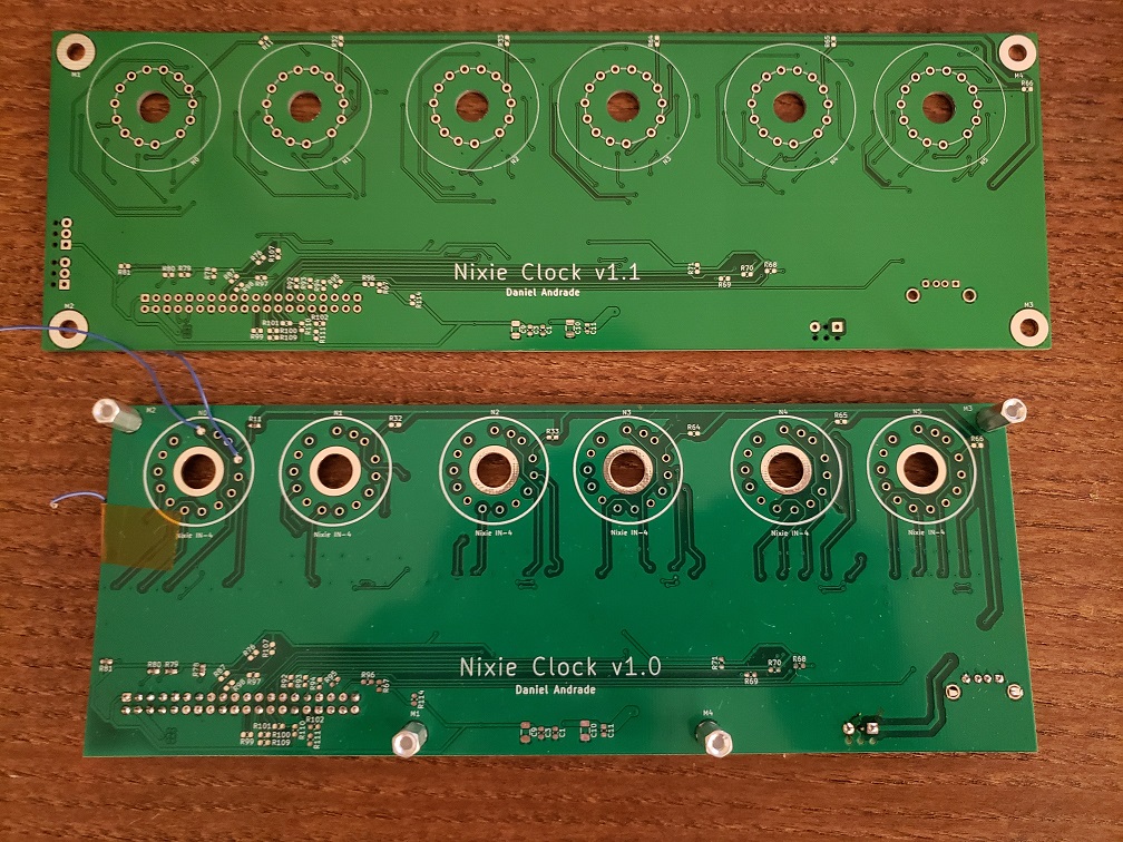
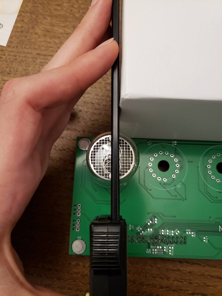
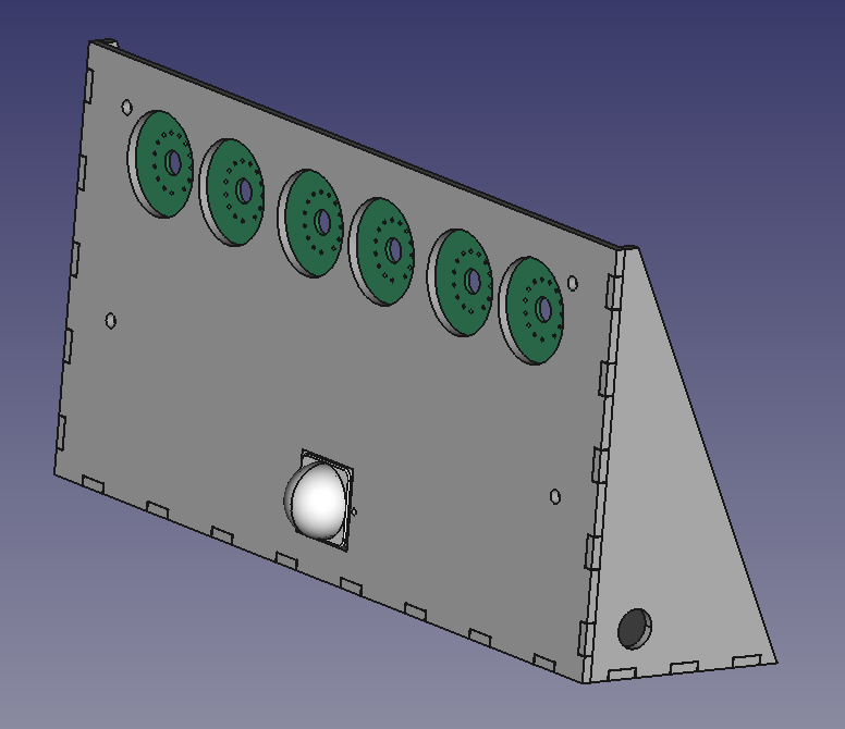
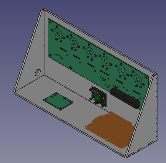
I did a quick fit test with the board and some standoffs and it looks pretty good. I’m so happy that my cut-outs for the tubes and the PIR sensor worked out well!
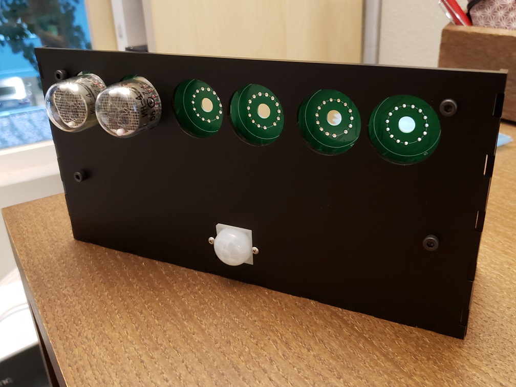
Front view 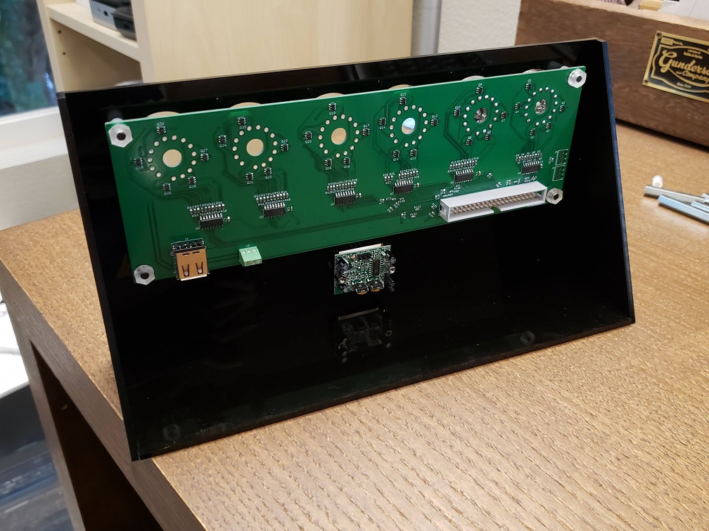
Back view
I’m very impressed with the material and with the laser cutting service. Everything fit well (if I were to remake this, I would probably shave a quarter mm from the joints as they were a little tricky to put together, but that’s on me) and I’m very happy with how it looks. Here’s some more detail on the material, which has a matte (external) and glossy (internal) side. I chose to put the matte side on the exterior because I don’t want my fingerprints all over the face of the clock, but there’s one face (the triangular face on the left) that’s inverted due to the orientation it was in when it was cut – something to thing about for next time.
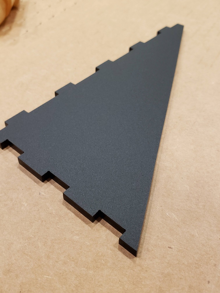
Matte side 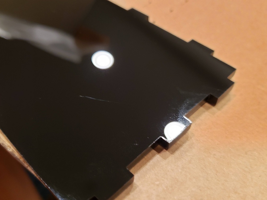
Glossy side
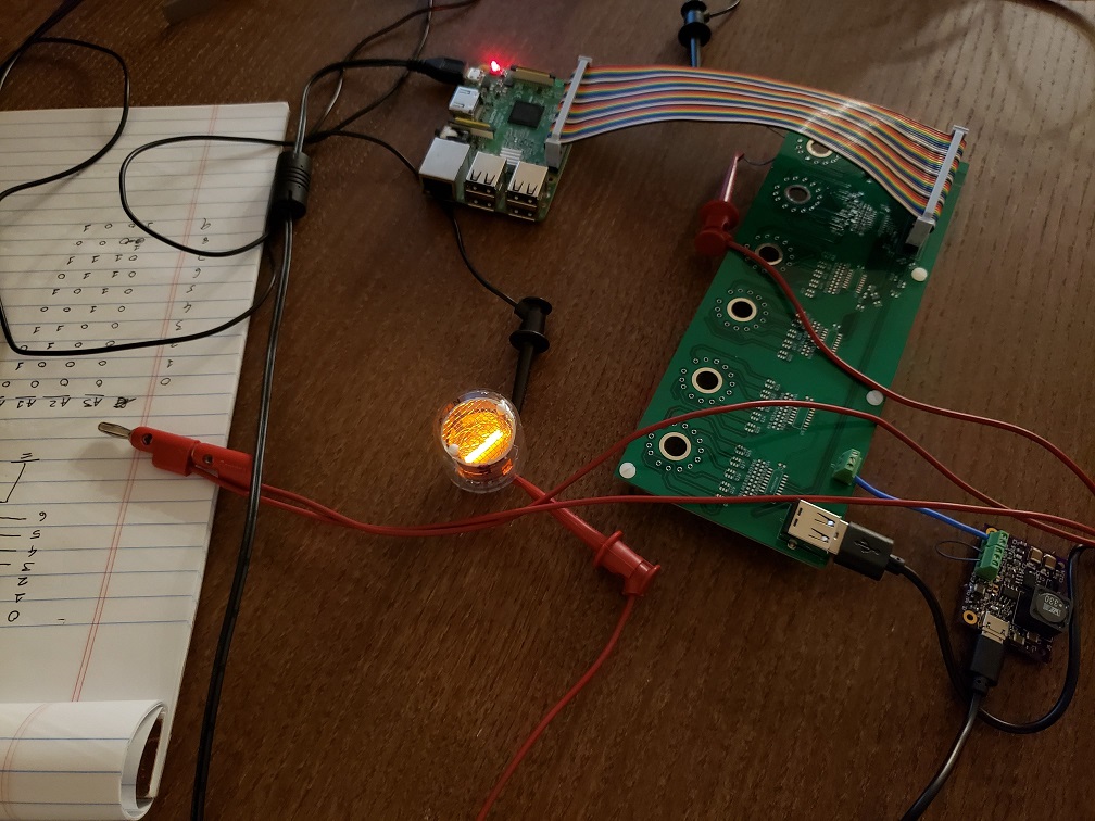
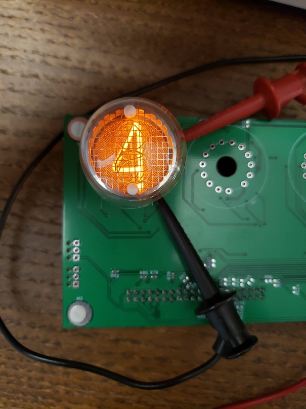
I also wrote a quick script to display the seconds portion of the current time on the two tubes I’ve got soldered down, and that”s worked well except for some digits missing due to some questionable solder joints.
Displaying the current seconds rather than the hours
")
")

")